
-
-
Build the machine on a flat surface to ensure the frame is square.
-
Attach the V-Slot-2040-750mm to the back two holes on the Y-Plate-Right-Assembly using 2 x M5-Low-Profile-15mm bolts.
-
Attach the C-Beam-750mm to the four non-threaded holes on the Y-Plate-Right Assembly shown above using 4 x M5-Low-Profile-15mm bolts.
-
-
-
Before the Y-Plate-Left-Assembly can be attached, Tee-Nuts need to be inserted.
-
The Tee-Nuts should be inserted so that the flat face is facing outwards.
-
Insert 2 x Tee-Nuts in to the front facing top slot, 2 x Tee-Nuts in to the front facing bottom slot.
-
Slide the X-Carriage-Assembly onto the C-Beam-750mm in the orientation seen above.
-
Repeat Step 1 for the Y-Plate-Left-Assembly.
-
Recheck the bottom Eccentric-Spacer-6mms on the X-Carriage-Assembly to make sure they are touching the rail, there is no wobble, and that the X-Carriage-Assembly runs smoothly along the whole length of the C-Beam-750mm.
-
Place the X-Gantry Assembly onto a flat table. Check both Y-Plates are sitting flush with the table. Loosen the extrusions and adjust if needed.
Did anyone else find they had to fold the wire terminals flat so the C beam could fit? Hope that will still operate. Any ideas?
William Walshaw - Resolved on Release Reply
Look at step 4 to understand what the T nuts are for/where they go
Matthew Watson - Resolved on Release Reply
your saying 2080 x750 v slot i don’t have this . is this referring to the smaller of the workbees as i have the 1500 x 1500 so what is it that im meant to use??
joe crampton - Resolved on Release Reply
Is worth looking at the ‘wire routing - step 2’ section first, as the z-limit switch wire needs to be routed through the front plate of its front-plate. Do this before assembling a axis onto c-beam.
Adrian Hardy - Resolved on Release Reply
Did you find that when you put yours together you had to bend the wires completely flat so they would not rub?
These images make it difficult to understand where the Tee-Nuts need to go. For those wondering, they go into the “back” of the C-Beam (the closed side, not the open side of the C). In terms of the channels you need, it’s the two most outer channels.
ashtonberry - Resolved on Release Reply
-
-
-
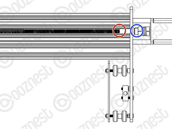
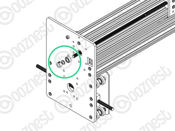
Looking at the Y-Plate-Left, adjust the X-ACME-Screw so the end is on the extrusion side of the Y-Plate-Left.
-
In the gap between the Y-Plate-Left and Flexible-Coupler, insert a F688zz-Bearing, 8mm-Shim, and 8mm-Clamping-Collar. With the F688zz-Bearing closest to the Y-Plate-Left, seated inside the hole.
-
Adjust the X-ACME-Screw back through the F688zz-Bearing, 8mm-Shim, and 8mm-Clamping-Collar, until there is gap of ~1.0mm (The thickness of a Precision-Shim) between it and the shaft of the NEMA23-Stepper-Motor shaft.
-
While pushing the 8mm-Clamping-Collar against the 8mm-Shim and F688zz-Bearing into the recess on the Y-Plate-Left, tighten the clamping bolt on the 8mm-Clamping-Collar.
-
Push the Flexible-Coupler up against the 8mm-Clamping-Collar. Tighten the clamping bolt first around the X-ACME-Screw, then the grub screw onto the X-ACME-Screw.
-
Rotate the Flexible-Coupler a couple of times to insure it is in a un-stressed state. Then rotate it so the grub screw on the stepper motor side is aligned with the flat portion of the motor shaft. Tighten the clamping bolt first around the motor shaft, then the grub screw onto the flat portion of the motor shaft.
-
On the outside of the Y-Plate-Right slide on a F688zz-Bearing, 8mm-Shim, and 8mm-Clamping-Collar. Inset the F688zz-Bearing into the hole.
-
While pushing the 8mm-Clamping-Collar against the 8mm-Shim and F688zz-Bearing into the recess on the Y-Plate-Right, tighten the clamping bolt on the 8mm-Clamping-Collar.
remove the grub screw and turn till you see the fat part of the shaft .
joe crampton - Resolved on Release Reply
Got to agree with Bruno. This could be worded/pictured better and it is actually easier dismantling parts we have already constructed. Why not just leave them until this part and then you can actually tighten the screws, find the flat of the shaft and make sure everything sits tight without so much delicate fiddling…
“Tighten the clamping bolt first around the motor shaft, then the grub screw onto the flat portion of the motor shaft.”. Since the Flexible-Coupler is covering most of the motor shaft, you can’t really tell which is the flat part unless you remove the motor and rotate the shaft manually.
-
-
-
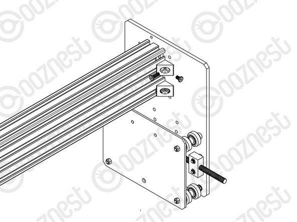
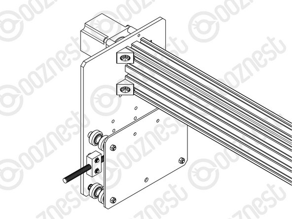
Attach an Angle-Corner to the Y-Plate-Right-Assembly & the front facing top slot of the C-Beam-750mm. A M5-Low-Profile-8mm screws into the Tee-Nut previously inserted, and a M5-Low-Profile-15mm goes though the Angle-Corner and attaches to a M5-Nyloc-Nut on the outside of the Y-Plate-Right-Assembly.
-
Repeat this for the other 3 Angle-Corners in the positions shown above.
For those wondering, they go into the “back” of the C-Beam (the closed side, not the open side of the C). In terms of the channels you need, it’s the two most outer channels.
ashtonberry - Resolved on Release Reply
-


Thanks for following the guide. Any issues, please contact us!
Thanks for following the guide. Any issues, please contact us!
Cancel: I did not complete this guide.
50 other people completed this guide.

3 Comments
Note that adding the end cap for the X gantry screw thread (opposite end to the stepper motor) is not referenced here - it is added after the screw threads have been tensioned - you can add the cap here to protect the end of the thread . The cap is mounted using the four remaining threaded holes in the X end plate. The cap has one side with two ‘U’ cut outs that go around the heads of the bolts that were use to join the plate to the C beam.
The ACME Endcaps are added during testing as you will need access to the leadscrews for tensioning.