
-
-
Insert 4 x M5-Button-Head-Bolt-12mm through the holes on the Controller-Case-Body
-
Slightly thread a M5-Drop-In-Tee-Nut onto each bolt.
-
-
-
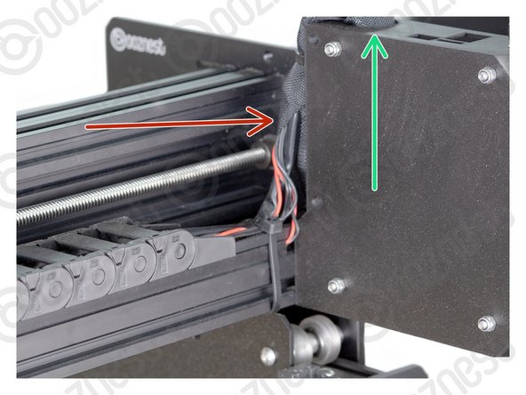
Join the Controller-Case-Body to both slots on the back of Extrusion-B. Using the previously inserted M5-Button-Head-Bolt-12mm.
-
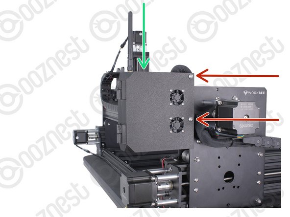
It should be pushed up against the Y-Carriage. See Image 2.
-
Using a 3mm Hex Key Ball driver would be easiest.
-
Make sure the M5-Drop-In-Tee-Nuts are engaged with the slots on Extrusion-B.
-
-
-
If you have the Wifi version, the External-Antenna is made up of 5 pieces: Antenna-Arm, Antenna-Wire, Spring-Washer, Star-Washer and Hex-Nut.
-
For the Wifi version, before putting the Controller inside the Controller-Case plug the Antenna-Wire into the Wifi module until it clicks.
-
Insert the supplied SD Card into the SD Card reader on the Controller.
-
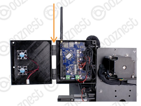
Mount the Controller to the Controller-Case-Body using 4 x M4-Cap-Head-Bolt-16mm and 4 x M4-Nyloc-Nut.
-
The 4 x M4-Nyloc-Nuts go on the back of the Controller-Case-Body.
-
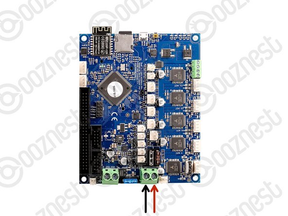
Make sure the Controller is orientated correctly with the two large green terminals at the bottom.
-
-
-
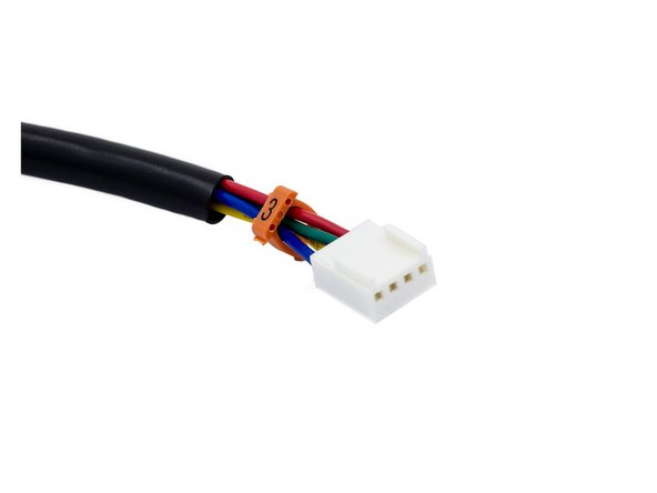
Gather all the wires coming of Drag-Chain-Y as well as Motor-Wire-3
-
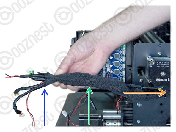
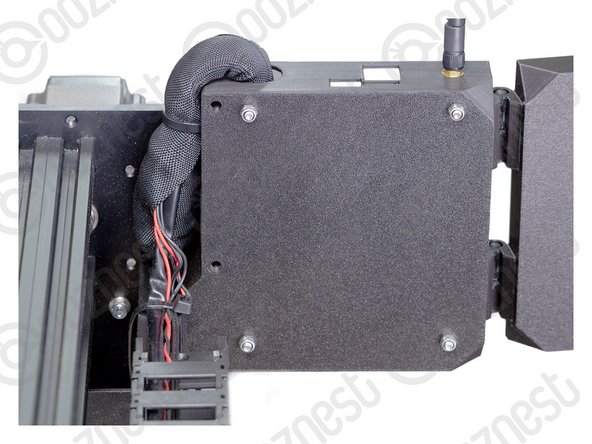
Neatly twist the wires together to form a consistent cylinder of wires. It should look like Image 1.
-
Include the Ethernet-Cable in this bundle.
-
Wrap the provided Cable-Sleeve around all the wires. It should look like Image 2.
-
The Cable-Sleeve should not go right to the end.
-
Excess Cable-Sleeve can go inside Drag-Chain-Y.
-
-
-
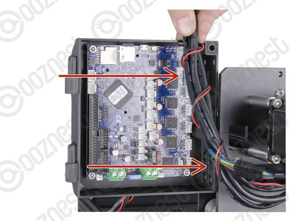
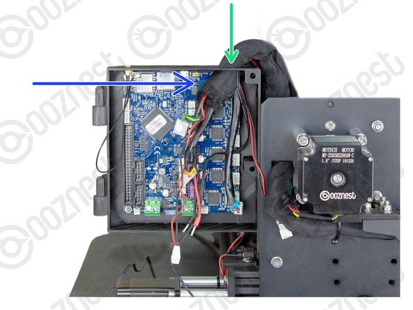
Feed the twisted bundle of wires through the square hole on the Y-Carriage.
-
Then run it up the side of the Controller-Case-Body and into the large hole on the top.
-
Do not put the Ethernet Cable through this hole. Slip it out of the Cable-Sleeve.
-
Roughly 50mm of Cable-Sleeve should be protruding into the Controller-Case-Body.
-
Take your time to tidy up the Cable-Sleeve, and feed any back into the Drag-Chain-Y.
-
-
-
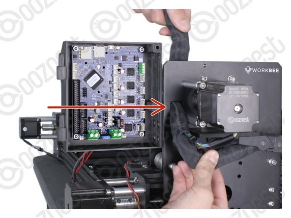
Bring the wires from Drag-Chain-X & Limit-Switch-0, up into the side of the Cable-Sleeve.
-
Feed them through the same hole in the top of the Controller-Case-Bod
-
Include the Touch Probe wire in this Step.
-
If at any point the wires are too short, 1-2 links can be removed from the corresponding drag chain.
-
-
-
You are going to need our Motor Wire and Limit Switch Cheat Sheet. We recommend printing it off!
-
-
-
Remember we have not told you to plug the power supply in yet, so please make sure it is not!
-
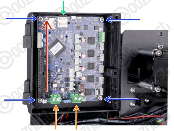
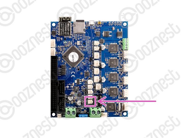
Connect the output wire of the Emergency-Stop into the input screw terminal on the Controller.
-
Use an Insulated Flathead Screwdriver.
-
-
-
The connectors on the wires are keyed, so there is only one way which they can plug in.
-
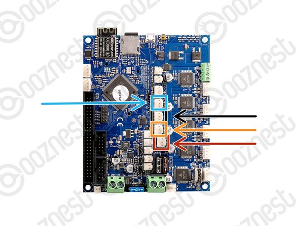
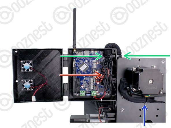
Plug in the limit switch wires following Image 1.
-
Limit-Switch-0 (X-Axis)
-
Limit-Switch-1 (Y-Axis)
-
Limit-Switch-2 (Z-Axis)
-
The Touch Probe wire can also be plugged in.
-
-
-
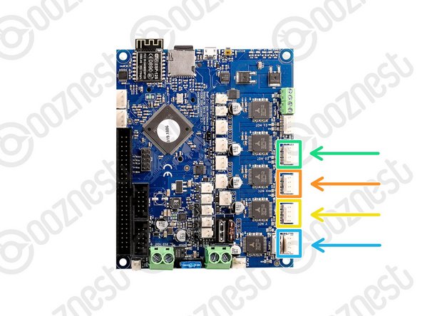
Plug in the motor wires following Image 1.
-
Motor-Wire-5 (Y-Axis-Right)
-
Motor-Wire-3 (X-Axis)
-
Motor-Wire-4 (Y-Axis-Left)
-
Motor-Wire-6 (Z-Axis)
-
-
-
If you have the Wifi Controller please complete this Step. Otherwise, skip to the next Step.
-
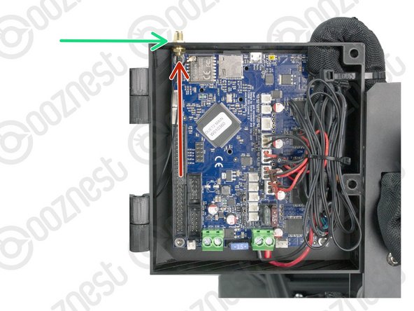
Inside the External-Antenna bag, there will be the Antenna-Arm, Antenna-Wire, Spring-Washer, Star-Washer and Hex-Nut.
-
Insert the threaded portion of the Antenna-Wire up into the hole of the Controller-Case-Body.
-
The Spring-Washer should be in between the shoulder of Antenna-Wire and Controller-Case-Body.
-
On the outside of the Controller-Case-Body add the Star-Washer, and then thread on the Hex-Nut.
-
Tighten this assembly.
-
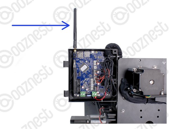
Screw on the Antenna-Arm.
-
-
-
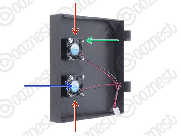
Mount the Controller-Fans to the Controller-Case-Cover using 8 x M3-Button-Head-Bolt-16mm & 8 x M3-Nyloc-Nut.
-
The Controller-Fans go on the inside of the Controller-Case-Cover.
-
The M3-Nyloc-Nuts should be on the inside of the Controller-Case-Cover. See Image 1.
-
The stickers on the Controller-Fans should be visible. See Image 1
-
Hook the Controller-Case-Cover onto the hinges on the Controller-Case-Body.
-
-
-
Bundle the excess cable inside the Controller-Case and add a small cable tie around the bundle.
-
On the side of the Controller-Case use a large cable tie to secure the bundle of wires inside of the Cable-Sleeve to the Controller-Case.
-
The large cable tie should go around the Cable-Sleeve bundle inside and outside the Controller-Case to sandwich it all together.
-
Tidy up the Cable-Sleeve on the outside controller and feed any excess back into Drag-Chain-Y.
-
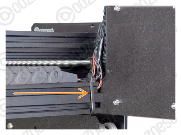
Use a large cable tie to secure the bundle to the Drag-Chain-Mount.
-
Use a large cable tie to secure the wires from Drag-Chain-X & Limit-Switch-0 to Extrusion-B
-
Make sure your wires look nice and neat like all the Images.
-
-
-
Plug the Controller-Fans into the Controller following Image 1.
-
Close the Controller-Case-Cover to the Controller-Case-Body.
-
Secure it using 2 x M5-Button-Head-Bolt-60mm and 2 x M5-Nyloc-Nut.
-
The 2 x M5-Nyloc-Nuts go on the back of the Controller-Case-Body.
-
If you have the Ethernet version of the controller, you can now plug the Ethernet-Cable into the top of the Controller.
-
-
-
That is the fiddly bits done! Now the exciting part....
-
Guide Complete
-
Wifi Controller:
-
Window Users - Proceed to 1. Connecting your Controller via USB - Windows
-
Mac Users - Proceed to 1. Connecting your Controller via USB - MacOS
-
Ethernet Controller:
-
Proceed to 1. Connecting your Controller to a Network - Ethernet
-


Thanks for following the guide. Any issues, please contact us!
Thanks for following the guide. Any issues, please contact us!
Cancel: I did not complete this guide.
47 other people completed this guide.

11 Comments
Having spent the last couple of days taking my time building my Z1+ 750x750 I've been impressed with the quality of the components until tackling the cable routing and controller assembly. Having assembled an Openbuilds 1510 a couple of years ago I found the Ooznest cables seemed to be short, and the control box a very poor quality 3d print, I also did not use the cable wrap as it just seemed to get in the way making what was already a rather annoying job much more difficult, I have some split flexi conduit knocking around and I'm going to use that instead. The Black Box controller is so much easier to wire as you just basically plug everything into the connections on the outside of the box. I understand that the Duet controller is very good but I cant help but feel that a larger case with proper access or even external connectors would work so much better. Cable just 150mm longer would help immensely.
Lea Newton - Resolved on Release Reply
I agree with the other comments, motor cable 5 and limit switch 0 were too short and the slack on the Y drag chain wires were not as long as the instructions would suggest.
Also I would like to see a better quality of controller box. Looks 3D printed and feels cheap which is a shame considering the rest is of such high quality.
Maybe the way the controller box is fastened onto the machine could be better, in particular the use of drop in t nuts. They didn't tend to spin for me to engage so had to put them in first which makes it difficult to local and screw in.
Loving the build but this section has let the rest down. Only my opinion of course and maybe no one else has found it an issue.
Richard Jackson - Resolved on Release Reply
Hi just finished wiring the controller, I found that after looking at your pictures and reading your instruction I was concerned that I would not get all the wiring nice and tidy, so the way I did it was to have all the wires just outside the controller box then (1) routed and attached the power cable (2) gathered and routed all the limit switch cables and attached them to the board (3) gathered and routed all the motor cables and attached them, while at the same time gathering them up to the right hand side inside the control box. It made the wiring much more easier as you can adjust the wire length as you route them.
regards David Boyd
Daivd Boyd - Resolved on Release Reply
I agree with Darren. Cable 5 no way near long enough on my 1500 x 1500. My first adventure into CNC and I am not overly comfortable making extensions now. not sure what to do. Maybe cut holes in the control box and purchase some more cable sleeve for the cables that will not comfortably reach the top hole. Overall this is stress city for me
Hi Richard,
Thanks for your comment, how long is your cable 5? And what machine have you got? It should be long enough.
Some users take a few links out of the y-axis drag chain to gain the extra length needed.
Robert
Robert -