
-
-
Insert 4 x M5-Button-Head-Bolt-12mm through the holes on the Controller-Case-Body
-
Slightly thread a M5-Drop-In-Tee-Nut onto each bolt.
-
-
-
Join the Controller-Case-Body to both slots on the back of Extrusion-B. Using the previously inserted M5-Button-Head-Bolt-12mm.
-
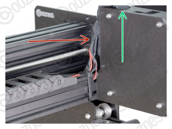
It should be pushed up against the Y-Carriage. See Image 2.
-
Using a 3mm Hex Key Ball driver would be easiest.
-
Make sure the M5-Drop-In-Tee-Nuts are engaged with the slots on Extrusion-B.
drop in t nuts again. Please find a better way as these are horrible
Richard Jackson - Resolved on Release Reply
align with the slot and push in,
then unscrew completely while applying pressure to the part and tighten again,
this will properly turn and tighten the drop in T-nuits
Mark -
-
-
-
If you have the Wifi version, the External-Antenna is made up of 5 pieces: Antenna-Arm, Antenna-Wire, Spring-Washer, Star-Washer and Hex-Nut.
-
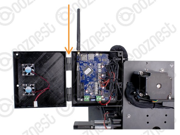
For the Wifi version, before putting the Controller inside the Controller-Case plug the Antenna-Wire into the Wifi module until it clicks.
-
Insert the supplied SD Card into the SD Card reader on the Controller.
-
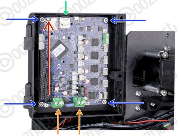
Mount the Controller to the Controller-Case-Body using 4 x M4-Cap-Head-Bolt-16mm and 4 x M4-Nyloc-Nut.
-
The 4 x M4-Nyloc-Nuts go on the back of the Controller-Case-Body.
-
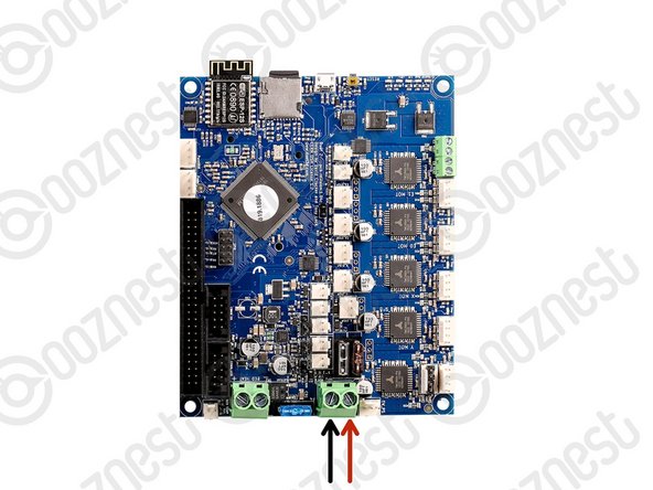
Make sure the Controller is orientated correctly with the two large green terminals at the bottom.
After rolling forward a couple more steps it didn’t look like I would ever be able to get the emergency stop connectors into the power inputs, so I ended up taking out three of the screws (leaving just the top right) which gave plenty of movement to be able to get them in neatly.
-
-
-
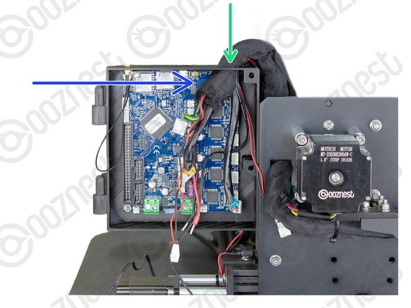
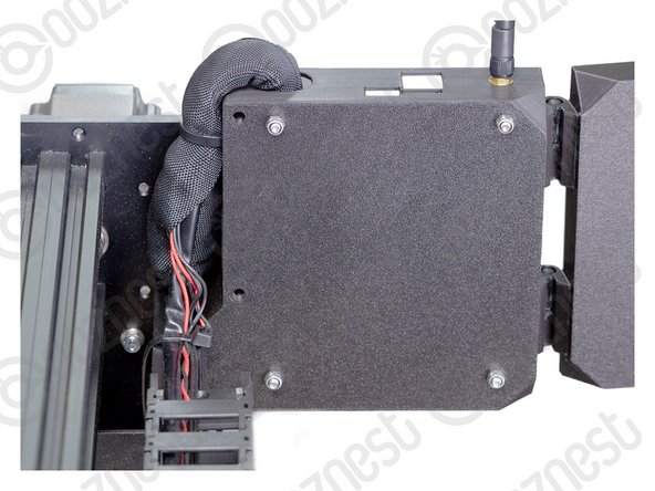
Gather all the wires coming of Drag-Chain-Y as well as Motor-Wire-3
-
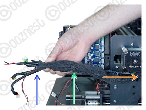
Neatly twist the wires together to form a consistent cylinder of wires. It should look like Image 1.
-
Include the Ethernet-Cable in this bundle.
-
Wrap the provided Cable-Sleeve around all the wires. It should look like Image 2.
-
The Cable-Sleeve should not go right to the end.
-
Excess Cable-Sleeve can go inside Drag-Chain-Y.
The wiring has to be the most difficult and frustrating parts of the whole build, trying to feed the bundle through the opening barely big enough for say 3 plugs, with 6 along with the sheathing was testing at best, only to then find in the next step you had to then include the probe, Ethernet cable and Z axis cables too, meant I had to pull it all out and start again.
This step should include the X axis Motor Wire in the wire bundle
Stephen White - Resolved on Release Reply
Regarding a 1500 x 1500 machine, motor wire 5 needs at the very least 100 mm more just to reach the terminal. And that is without the looming sheath. So maybe 150mm more. As it is right now, the plug end just meets the hole and there is zero slack in the line from the motor to the entry hole on the controller housing. Before you ask, the wire from the stepper motor is at the bottom position. Limit switch 0 and 2 would also benefit from having 80-100 mm more in length. If I zip tied limit switch 2 to extrusion B as instructed, then it is too short. As it is, if you had to re-terminate a wire, there is zero service loop length.
Jacob Weiand - Resolved on Release Reply
Hi Jacob,
The wires supplied are the correct lengths needed to assemble the WorkBee. If you are coming up drastically short, you may have received the wrong set of wires for your size machine. Please contact us at https://ooznest.co.uk/help/ where we can help resolve this issue.
Thanks.
The length of slack on the 1500 x 1500 machine is far too little. X axis limit switch, motor cable 5 and e stop cable needs to be longer.
Richard Jackson - Resolved on Release Reply
-
-
-
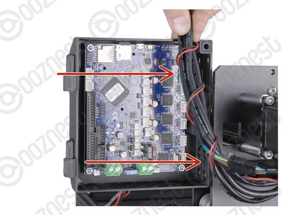
Feed the twisted bundle of wires through the square hole on the Y-Carriage.
-
Then run it up the side of the Controller-Case-Body and into the large hole on the top.
-
Do not put the Ethernet Cable through this hole. Slip it out of the Cable-Sleeve.
-
Roughly 50mm of Cable-Sleeve should be protruding into the Controller-Case-Body.
-
Take your time to tidy up the Cable-Sleeve, and feed any back into the Drag-Chain-Y.
I am really struggling with this part of the assembling.
Most of the cables coming of my Drag-Chain-Y are too short (and there is no excess length at the oter ends).
Would it be possible that the Drag-Chain-Y is too long ? That's my feeling...
Alain Borgnet - Resolved on Release Reply
I honestly dont understand why we’re told to include the ethernet in the cable buncle in one step then told to remove it in the next. Seems kinda pointless?
D'Jay Fleury - Resolved on Release Reply
Hi D’Jay, Thanks for your comment. This step is referring to the hole in the controller case. So you put the Ethernet Cable first through the hole in the Y-Plate on the previous step. But you do not put it through the hole in the controller case. Hope that clears it up.
Robert -
-
-
-
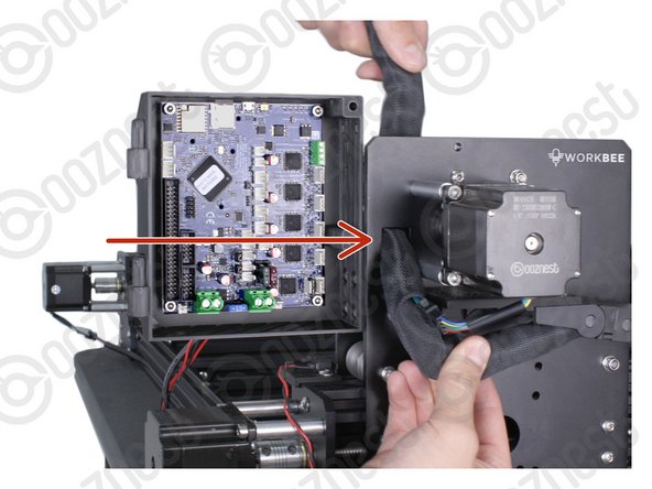
Bring the wires from Drag-Chain-X & Limit-Switch-0, up into the side of the Cable-Sleeve.
-
Feed them through the same hole in the top of the Controller-Case-Bod
-
Include the Touch Probe wire in this Step.
-
If at any point the wires are too short, 1-2 links can be removed from the corresponding drag chain.
If you have a Touch Probe that wire needs to be routed into the controller box in this step.
Chris McMahon - Resolved on Release Reply
In addition to the above comment, by drilling the new 1” diameter hole it gained me approximately 60mm of extra wire length inside the box.
Tom Hawkins - Resolved on Release Reply
When I routed my wires this way, I ended up not having enough wire length to reach the respective terminals. I took a 1” diameter Forstner bit and drilled a hole into the right side of the box just below the two wire tie holes. The wires then reached all the terminals.
Tom Hawkins - Resolved on Release Reply
I feel like this is a strange way to do this. Trying to stuff these X cables into the bundle, sleeve and already crowded hole was a lot harder than it would have been to bundle ALL of the cables in the sleeve and push it in as one, with clips offset obviously.
I dont know if the hole in my controller box is smaller than it’s supposed to be but man… you guys need to make it at least a hair bigger. Maybe oval shape? Cause whichever way you do it that is way too tight of a fit. Despite being extra careful, I feel like i was way rougher than i ever would have liked with some of the cables just to make this work.
D'Jay Fleury - Resolved on Release Reply
Hi D’Jay, thanks for your feedback. It may be easier to put the connectors through the whole one at a time. Once all through, the wires should take up ~2/3 of the hole. Robert
Robert -
-
-
-
You are going to need our Motor Wire and Limit Switch Cheat Sheet. We recommend printing it off!
-
-
-
Remember we have not told you to plug the power supply in yet, so please make sure it is not!
-
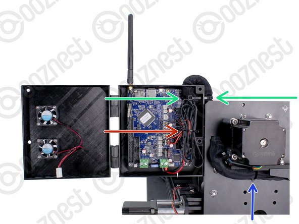
Connect the output wire of the Emergency-Stop into the input screw terminal on the Controller.
-
Use an Insulated Flathead Screwdriver.
Gday guys, probably good to tell the users to do it before screwing the MOBO in the 3D printing case. It makes it almost impossible to feed the out wires in the MOBO port... Thank you :D
Jean-Eudes - Resolved on Release Reply
Could not agree more. Why not make the controller case a little higher to allow room for these wires? They are unnecessarily tricky to get in !!!
David Van Der Wee, I am glad you made the above comment. It made me look at the configuration and guess what ….. I had put the wires in the wrong way round. So thank you!!
patkempe@uwclub.net - Resolved on Release Reply
For old boys like me who print the instructions on a mono laser, you dont get the polarity information of the power supply. Pop go the fuses, luckily no other damage though. Might be a good idea to put Positive and Negative in the text.
David Van Der Wee - Resolved on Release Reply
Luckily I did this from the iPad so I had a colour screen to go off, but a simple + and - on the image would be better.
-
-
-
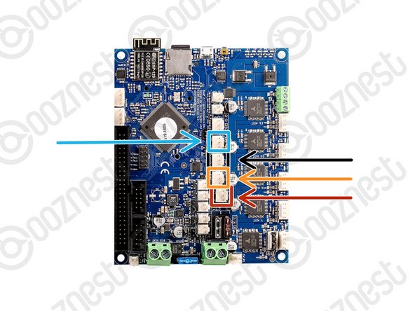
The connectors on the wires are keyed, so there is only one way which they can plug in.
-
Plug in the limit switch wires following Image 1.
-
Limit-Switch-0 (X-Axis)
-
Limit-Switch-1 (Y-Axis)
-
Limit-Switch-2 (Z-Axis)
-
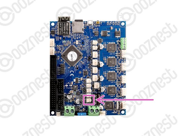
The Touch Probe wire can also be plugged in.
Hi there, we have an issue with the Z limit switch, says it's always triggered? Checked where it's plugged in and that's definitely correct, anyone know how to fix?
Gareth Simmonds - Resolved on Release Reply
Hi Gareth,
I'm sorry to hear this. It looks like the Z-axis limit switch is damaged. You can buy a replacement here: https://ooznest.co.uk/product/original-w.... If your machine is still within our warranty, we're happy to help you with a replacement. Please reach out to us at help@ooznest.co.uk or use the one of the contact forms here: https://ooznest.co.uk/help/
I hope this helps!
Cyndy -
Nearly every wire for the motors and limit switches are too short for me on the 1000x1500 not to sure if i’ve done something wrong but i’ve looked at it for a whole day now and still no idea or if my wires are just to short
Hi Ajay,
Thanks for your message.
They should be long enough. Could you email us a picture please of the wiring and we can check it for you.
Thanks
Motor cable 5 is too short on the 1500 x 1500 needs to be about 75mm longer
Richard Jackson - Resolved on Release Reply
The touch probe wire is dual black with double pin connector.
The blue square in the above drawing is marked for a 3-pin white socket, so can’t be correct. There is a 2-pin connector to the left of the blue square so I’ll try using that.
Thanks Robert, I think I’ve sorted this. The white 3-pin connector from the touch probe goes into the blue square. The black 2-core wire from the 5cm square Al touch probe plate plugs into the socket below the router motor
Hi,
Are you using our Touch Probe? as ours is a 2-wire, 3-pin connector. so it must go where indicated by the blue square.
Robert -
Out limit switch-1 cable had a brown tag rather than orange.
Chris McMahon - Resolved on Release Reply
some of the wires on the 1500 x 1500 version could do with another 50mm in length
David Van Der Wee - Resolved on Release Reply
-
-
-
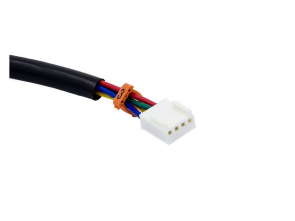
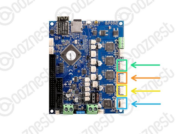
Plug in the motor wires following Image 1.
-
Motor-Wire-5 (Y-Axis-Right)
-
Motor-Wire-3 (X-Axis)
-
Motor-Wire-4 (Y-Axis-Left)
-
Motor-Wire-6 (Z-Axis)
-
-
-
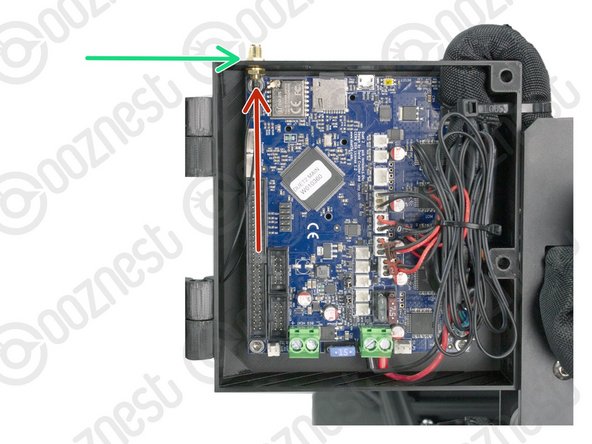
If you have the Wifi Controller please complete this Step. Otherwise, skip to the next Step.
-
Inside the External-Antenna bag, there will be the Antenna-Arm, Antenna-Wire, Spring-Washer, Star-Washer and Hex-Nut.
-
Insert the threaded portion of the Antenna-Wire up into the hole of the Controller-Case-Body.
-
The Spring-Washer should be in between the shoulder of Antenna-Wire and Controller-Case-Body.
-
On the outside of the Controller-Case-Body add the Star-Washer, and then thread on the Hex-Nut.
-
Tighten this assembly.
-
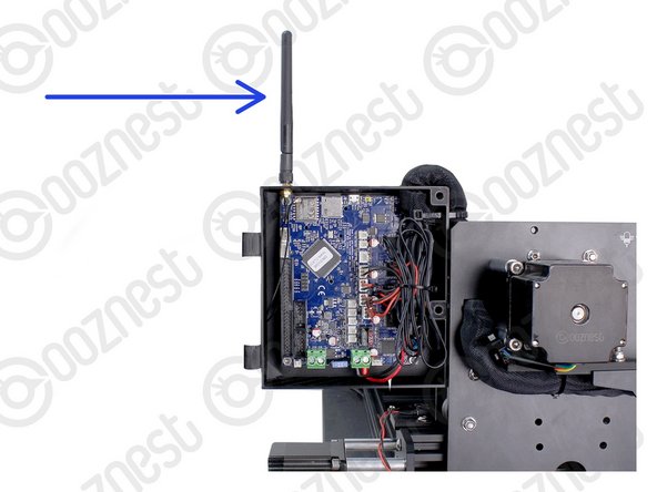
Screw on the Antenna-Arm.
The antenna connector takes seconds to fit if the controller isn't screwed into the case. A gentle squeeze between fingers and it slides home into the socket. I doubt that the average adult male can achieve this with the controller in the case.
I also suggest modifying the design of the case "bottom" (the bit the controller board screws into) in 2 parts, so the cable hole is open during building but has a screw in bridge to hold the cables after they have all been fitted. This would allow more cables to pass into the case without having to push headers through the an ever decreasing gap.
John Clegg - Open Reply
3 years later and I am hitting the same issue connecting the antenna wire. As suggested this should have been done earlier with the controller outside! I was 50/50 Ethernet Wifi and now seriously regretting choosing WiFi.
John Clegg - Open Reply
Had the same problem and thought the plug/socket was damaged. The spring in the wire didn’t help. Also the picture does not represent the pcb which was shipped as the socket / chip is in a different orientation.
My solution in the end was disconnect everything and pull the card so I could fit it on the bench, then reassemble. This was the low point of the build but minutes later it was moving under its own power so all forgiven ;-)
Gary Curtis - Resolved on Release Reply
Do you think it would be beneficial to take the control board off and try to connect and replace once connected
Anthony Broderick - Resolved on Release Reply
There does not seem to be any damage to the parts the connections are that small and shallow I am finding it difficult to align and it just pops off
Anthony Broderick - Resolved on Release Reply
I have been trying to connect the antenna wire onto the control board for the past 2 days without success. Is there a easy way of completing this action
Anthony Broderick - Resolved on Release Reply
-
-
-
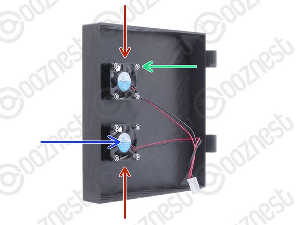
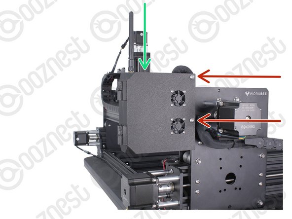
Mount the Controller-Fans to the Controller-Case-Cover using 8 x M3-Button-Head-Bolt-16mm & 8 x M3-Nyloc-Nut.
-
The Controller-Fans go on the inside of the Controller-Case-Cover.
-
The M3-Nyloc-Nuts should be on the inside of the Controller-Case-Cover. See Image 1.
-
The stickers on the Controller-Fans should be visible. See Image 1
-
Hook the Controller-Case-Cover onto the hinges on the Controller-Case-Body.
Mount the Controller-Fans as loosely as possible (while still engaging the Nyloc) to the Controller-Case-Cover to avoid pinching the plastic housing and blocking the rotation of the fans.
The fans are located over the wire harness. Makes air ventilation poorer and fitting packaging harder.
once I managed to get the wiring in and trying to close the cover … which was difficult, I also noticed the fans are on top of the wiring bundle and with nowhere else to put the bundle, as there’s no room and no slack… I had to close the door and hope for the best.
Making the cover 10mm deeper or perhaps adding 20mm to the width on the right side of the case would allow the wiring bundle to sit to the right of the motherboard and be pressed further to the back of the case, you could then also put a couple of small holes to cable tie the bundle to the back of the case, all of that would improve air circulation dramatically, even mounting the fans an inch to the left would allow them to clear the bundle of wires inside.
Ooznest: Is there any chance we could download the 3d model files for the case (and all the other 3d printed components) in the spirit of open source, so we can make our own modified versions, or allow us to print new ones should any break through wear and tear etc?
I agree and it was a struggle to close the door with the fans impinging on the motor cables. Why can’t the fans be on the other side? Makes more sense.
I was thinking maybe to add some kind of a dust filter screen to the openings of the controller box (under the fans if they blow air into the box). Maybe something similar than server rack doors have, but have to first make sure it allows enough air to flow so i don’t cook anything on the controller board.
Jokke the Machinist - Resolved on Release Reply
Hi Jokke,
Yes you can do this. If you so it, just monitor the web interface for overheating warnings.
Robert -
-
-
-
Bundle the excess cable inside the Controller-Case and add a small cable tie around the bundle.
-
On the side of the Controller-Case use a large cable tie to secure the bundle of wires inside of the Cable-Sleeve to the Controller-Case.
-
The large cable tie should go around the Cable-Sleeve bundle inside and outside the Controller-Case to sandwich it all together.
-
Tidy up the Cable-Sleeve on the outside controller and feed any excess back into Drag-Chain-Y.
-
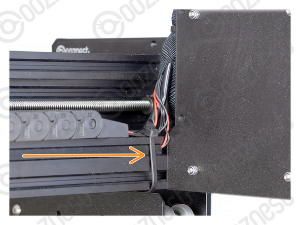
Use a large cable tie to secure the bundle to the Drag-Chain-Mount.
-
Use a large cable tie to secure the wires from Drag-Chain-X & Limit-Switch-0 to Extrusion-B
-
Make sure your wires look nice and neat like all the Images.
I had the same issue with the hinges. I also realized at the end that the hole in the bottom vents of the controller box was due to a broken box and not intentional. Not a big deal, but some of the layers in the printed controller box are a bit thin and susceptible to breakage.
Hinges on my box were too tight. check before you push them home as very difficult to get apart. I had to prise them off very carefully with a knife and then sand them down and drill them out . Bit of sand paper or a file does the job.
Hi Sam, Thanks for your feedback we will look into and revise the design to ensure this is resolved!
-
-
-
Plug the Controller-Fans into the Controller following Image 1.
-
Close the Controller-Case-Cover to the Controller-Case-Body.
-
Secure it using 2 x M5-Button-Head-Bolt-60mm and 2 x M5-Nyloc-Nut.
-
The 2 x M5-Nyloc-Nuts go on the back of the Controller-Case-Body.
-
If you have the Ethernet version of the controller, you can now plug the Ethernet-Cable into the top of the Controller.
The fan leads could stand to be longer, at least long enough to open the door all the way. I had to support the outer enclosure cover on the extrusion below to plug in the fans.
And yes, the the wire bundle is annoyingly in the way. How about incorporating a tie bar to the enclosure. Maybe a rod that gets installed in front of the duet board from top to bottom after the board is wired.
To keep the bundle of wires away from the fans, I used a several of the little zip ties to secure the wires. They essentially went in front if the wires, up through the SD slot opening, around the back, up through one of the cooling slots, and back to the beginning. Not super tight but just enough to hold things in their space.
Jacob Weiand - Resolved on Release Reply
holes sizes on the case cover fixings could do with being a tad larger.
David Van Der Wee - Resolved on Release Reply
I gotta say, it seems like a big oversight that both fans are directly on top of the whole cable bunch (likely also touching them once it’s closed)…
Totally agree, see my comments above. Moving the fans an inch to the left, or making the case 20mm wider so the bundle could sit to the right of the motherboard and be zip tied in place would be a huge win.
Wouldn’t take much effort to move them over the mainboard. That said, perhaps they’ve done a CFM analysis and this is best? If not, is the design available so we can modify the case lid?
Spoon -
-
-
-
That is the fiddly bits done! Now the exciting part....
-
Guide Complete
-
Wifi Controller:
-
Window Users - Proceed to 1. Connecting your Controller via USB - Windows
-
Mac Users - Proceed to 1. Connecting your Controller via USB - MacOS
-
Ethernet Controller:
-
Proceed to 1. Connecting your Controller to a Network - Ethernet
The controller case is intended to be installed by a double-jointed contortionist with tiny steel like fingers who can route large numbers of cables through small holes neatly and tidily. I’m not sure why devices like this with controller cases always try to use the smallest case size which limits the size of the cable holes. I had similar problems building a Prusa 3D printer. If the case were a bit bigger with a bigger cable hole the job would have been a lot easier and would have looked much neater.
Chris McMahon - Resolved on Release Reply
-


Thanks for following the guide. Any issues, please contact us!
Thanks for following the guide. Any issues, please contact us!
Cancel: I did not complete this guide.
47 other people completed this guide.

11 Comments
Having spent the last couple of days taking my time building my Z1+ 750x750 I've been impressed with the quality of the components until tackling the cable routing and controller assembly. Having assembled an Openbuilds 1510 a couple of years ago I found the Ooznest cables seemed to be short, and the control box a very poor quality 3d print, I also did not use the cable wrap as it just seemed to get in the way making what was already a rather annoying job much more difficult, I have some split flexi conduit knocking around and I'm going to use that instead. The Black Box controller is so much easier to wire as you just basically plug everything into the connections on the outside of the box. I understand that the Duet controller is very good but I cant help but feel that a larger case with proper access or even external connectors would work so much better. Cable just 150mm longer would help immensely.
Lea Newton - Resolved on Release Reply
I agree with the other comments, motor cable 5 and limit switch 0 were too short and the slack on the Y drag chain wires were not as long as the instructions would suggest.
Also I would like to see a better quality of controller box. Looks 3D printed and feels cheap which is a shame considering the rest is of such high quality.
Maybe the way the controller box is fastened onto the machine could be better, in particular the use of drop in t nuts. They didn't tend to spin for me to engage so had to put them in first which makes it difficult to local and screw in.
Loving the build but this section has let the rest down. Only my opinion of course and maybe no one else has found it an issue.
Richard Jackson - Resolved on Release Reply
Hi just finished wiring the controller, I found that after looking at your pictures and reading your instruction I was concerned that I would not get all the wiring nice and tidy, so the way I did it was to have all the wires just outside the controller box then (1) routed and attached the power cable (2) gathered and routed all the limit switch cables and attached them to the board (3) gathered and routed all the motor cables and attached them, while at the same time gathering them up to the right hand side inside the control box. It made the wiring much more easier as you can adjust the wire length as you route them.
regards David Boyd
Daivd Boyd - Resolved on Release Reply
I agree with Darren. Cable 5 no way near long enough on my 1500 x 1500. My first adventure into CNC and I am not overly comfortable making extensions now. not sure what to do. Maybe cut holes in the control box and purchase some more cable sleeve for the cables that will not comfortably reach the top hole. Overall this is stress city for me
Hi Richard,
Thanks for your comment, how long is your cable 5? And what machine have you got? It should be long enough.
Some users take a few links out of the y-axis drag chain to gain the extra length needed.
Robert
Robert -
Controller Box not dimensioned appropriately:
Getting the power cable to fit in the green block at the bottom is difficult because it’s so close to the case. I’ve seen others put a severe bend in the connector to get it to fit which is far from ideal when it comes to a power cable. If the box were a little taller it would help, or it would be better for the instructions to suggest fitting the power cable before securing the board in the box. Strangely the instructions tell you to put the SD card in first even though there's a slot in the box so you can insert this at any point.
The fans collide with the cables inside, a deeper lid would help this, or relocating them to the left, or even some tie down points at the far right to help cable management.
This is the hardest part for multiple reasons.
Cables too short: Tugging cables to get them to fit doesn't feel safe and I wonder if some get damaged by doing this. Particularly on my 1500x1500 the Motor-Wire-5 cable is too short to both fit in the extrusion and reach the controller board. I placed it in the extrusion slot as instructed only to discover in a later stage that it won’t reach the controller board. This meant I had to pull it out which is not pleasant as it was stuck in there so pulling it out again puts extra stress on the cable. Since this cable is now just flopping around behind the machine I’m going to have to make an extension for it at some point.
(continued in other post due to character limit)
This task is graded “Easy”. In principle that’s true: pass some wires through a couple of holes and plug them in. However, for me, it was the most difficult bit yet. The holes are very tight and it’s difficult to judge the lengths of cable required. Wrapping the cable sleeve around, with cables passing in and out, and tucking the excess into the drag chain was frustrating. Most irritating, I didn’t include Motor Wire 3 in the bundle. I don’t think the instructions say to do this, although, in truth, the picture does show it included. Putting it in retrospectively wasn’t easy. I also share concerns about the fans resting directly against the bundled up wires. However, it’s all done now and I’m looking forward to the next part when I get to plug it in. It’s looking good!
Hi Michael,
Thanks for your comment. We admit it can be a little difficult tidying the wires, but all worth it in the end when your cables look super tidy! For the wire being over the fans issue, if you keep the wires to the right-hand side of the controller as much as possible, then it will work perfect.
Robert -
Hi Ryan, Personally I would say that this was the most difficult of all the tasks as on the 1st attempt LS2 would reach and on the 2nd attempt motor wire 6 wouldn’t reach. 3rd time lucky. Overall its a neat assembly but I am a bit concerned about debris getting through the holes in the top of the controller case. Is it OK to place some fine mesh over these holes or just tape over them?
Ian Martin - Resolved on Release Reply
Same problem as above: filed the holes out a bit using a round file. Some of the counterbores were oval too and the bolt heads didn’t fit so had to scrape them out a bit. Might be an idea to slightly increase their diameter in the 3D model to compensate for this.
bart - Resolved on Release Reply
yep me too .
Neil Dilly - Resolved on Release Reply
Had “D” shaped holes. Ran 7/32” drill bit through the holes to open them up.
Tom Hawkins - Resolved on Release Reply