
-
-
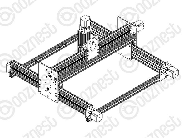
Slide a C-Beam-750mm through each set of wheels on the X-Gantry-Assembly. The Y-ACME-Screws go inside the ‘C’ Channel.
-
Rest the ends of the C-Beam-750mm on 2 x V-Slot-2040-745mm’s. The ends of the extrusions should be flush with the sides of each other.
-
-
-
If possible while carrying out the below steps get a second person to hold the machine square.
-
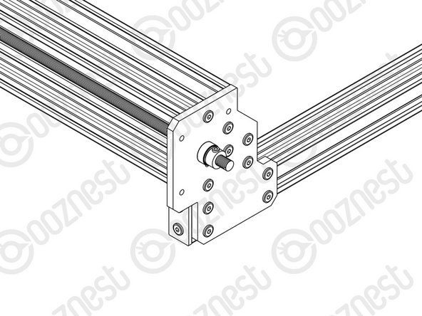
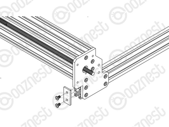
Slide the X-Gantry-Assembly to the front, and attach a Y-End-Plate to the front left corner, first using 4 x M5-Low-Profile-15mms, which screw into the tapped holes on the C-Beam-750mm.
-
Insert 2 x Tee-Nuts into the front facing top and bottom slots of the V-Slot-2040- 745mm. Adjust the Tee-Nuts so they line up with the holes on the Y-End-Plate.
-
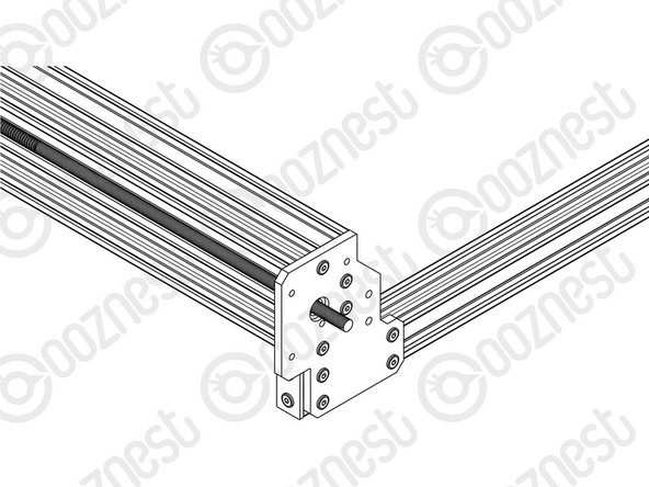
Secure the Y-End-Plate to the V-Slot-2040-745mm using 4 x M5-Low-Profile- 12mms. Ensure the end of the V-Slot-2040-745mm is flush with the side of the C Beam-750mm.
-
Square the base, and repeat for the Y-End-Plate on the opposite end of the front V-Slot-2040-745mm.
-
Slide the X-Gantry-Assembly to the back. Square the base, and repeat all the above for the back V-Slot-2040-745mm.
-
-
-
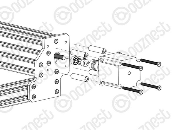
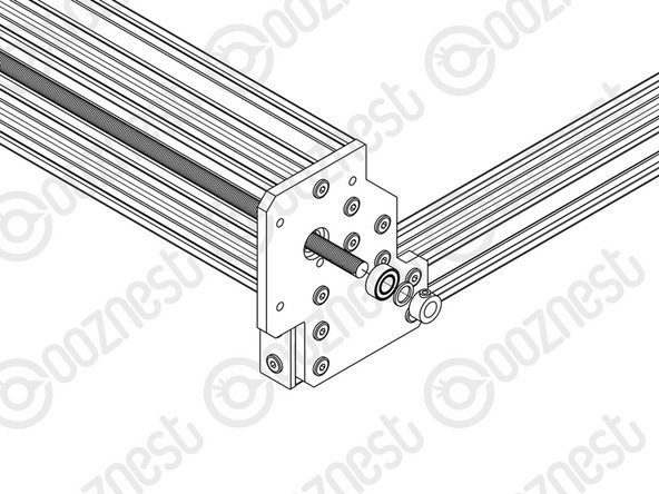
Adjust the left Y-ACME-Screw (as if looking from the front) so roughly 10mm is protruding from the Y-End-Plate at the back of the machine. Slide onto the end a F688zz-Bearing, 8mm-Shim and 8mm-Clamping-Collar, and inset the F688zz-Bearing into the hole on the Y-End-Plate.
-
Slide the 1/4” side (the side with the smallest hole) of the Flexible-Coupler onto the shaft of the NEMA23-Stepper-Motor. Don’t tighten it down at this point.
-
Attach the NEMA23-Stepper-Motor to the threaded holes on the Y-End-Plate using 4 x M5-Low-Profile-50mm bolts and 4 x Aluminium-Spacer-40mms. Adjust the Y-ACME-Screw so it is touching the NEMA 23-Stepper-Motor shaft.
-
Orient the NEMA23-Stepper-Motor so the wire is facing downwards.
-
While pushing the 8mm-Clamping-Collar against the 8mm-Shim and F688zz-Bearing into the recess on the Y-End-Plate, tighten the clamping bolt on the 8mm-Clamping-Collar.
-
Tighten the grub screws on the Flexible-Coupler. Make sure one is on the flat portion of the motor shaft.
-
Repeat for the final NEMA23-Stepper-Motor attaching it to the Y-End Plate-Left on the back right of the machine.
-
-
-
At the front of the machine, onto the two Y-ACME-Screws protruding from the Y-End-Plates slide on a F688zz-Bearing, 8mm-shim, and a 8mm-Clamping-Collar.
-
While pushing the 8mm-Clamping-Collar against the 8mm-Shim and F688zz-Bearing into the hole on the Y-Plate-End-Plates, tighten the clamping bolt on the 8mm-Clamping-Collar.
This drawing shows two bolt heads above the cross piece that disappear in step 5 drawing. I believe they are an artifact of a previous version. Confusing.
Mike Magnay - Resolved on Release Reply
Hello, I have a workbee I purchased in March 2019, at the time the instructions were to put the shim and collar on the other side of the plate. Is it possible to mount them as in this image - on the outside? Or do I need longer screws to do this?
Lyubomir Popov - Resolved on Release Reply
-
-
-
Attach an End-Cap to front left end of the V-Slot-2040-745mm using 2 x M5-Low-Profile-8mm bolts.
-
Repeat this for the other 3 x End-Caps on the other bare ends of the V-Slot-2040-745mms.
Actual photographs would be so mutch easier to see what is what. I have ask other member to take pictures. Maybe a suggestion :-)
Gregory Van der Auwera - Resolved on Release Reply
Thanks for the suggestion! We are always looking to improve the manuals where we can.
Don’t fix these end caps yet…..you need to slid in t-nuts during the next stage.
Jonathan Pearce - Resolved on Release Reply
-


Thanks for following the guide. Any issues, please contact us!
Thanks for following the guide. Any issues, please contact us!
Cancel: I did not complete this guide.
47 other people completed this guide.

One Comment
Step 5- End Caps, they need to be removed in order to do the steps in the next module. This step should be skipped for now.
Adam J Barnett - Resolved on Release Reply