
-
-
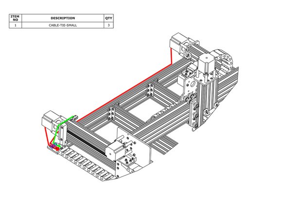
The Z-Limit-Switch sits in-between two sets of wheels. Directly opposite there is a hole. Feed the wires through this hole (red circle).
-
Pull the wire tight to prevent the wire rubbing on the C-Beam Extrusion.
-
As shown by the green line above bring the Z-Limit-Switch wires up the X-Plate-Back, and feed it through the X-Drag-Chain.
-
Secure the wires using Cable-Tie-Smalls to the points marked with blue circles. To stop it snagging on anything the wire should be pulled tight.
-
-
-
For the Z-Axis Motor Wire that is inside the X-Drag-Chain, connect it to the pigtail on Z-Axis stepper motor. Making sure there is enough slack for the full travel of the Z-Axis shown in red, secure the wire to the X-Drag-Moving-End-Mount using a Cable-Tie-Small, shown by the small blue circle above.
-
The lead on the X-Axis limit switch should be secured to the V-Slot-2040-750mm using a Cable-Tie-Large at the position shown by the blue oval above. Then run the lead along to the other end of V-Slot-2040-750mm - it can be tucked into one of the slots.
-
-
-
Connect the two stepper motor wires in the Y-Drag-Chain to their corresponding pigtails on the Y-Axis stepper motors. The longer wire should connect to the right hand stepper motor.
-
Secure the stepper motor wires to the Y-Axis-Fixed-End-Mount using Cable-Tie Smalls. The wire for the right hand stepper motor can be tucked into a slot on one of the extrusions along the back.
-
Secure the lead on the Y-Axis limit switch to the Y-Axis-Fixed-End-Mount using a Cable-Tie-Small.
our cables don’t reach the other side ( meaning the left hand will no way connect from the drag chain ) are the two black cables yellow and green meant to be in the drag chain on the right hand ( i am looking at it from the back )
Hi David, Can you send us some more details of your issue through the Contact us section here - https://ooznest.co.uk/help/#tab_technica... and the team can advise further.
-
-
-
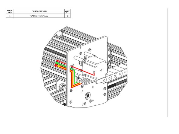
Connect the X-Axis motor wire to the pigtail on the X-Axis stepper motor and feed it through the square hole on the Y-Plate.
-
Inside the Y-Drag-Chain there should be two stepper motor wires (red line), a power supply wire (yellow line), and a limit switch wire (green line). Feed all of these through the square hole on the Y-Plate.
-
Remove any slack inside the Y-Drag Chain, and then secure these 4 wires to the Y-Drag-Chain-Moving-End-Mount using Cable-Tie-Smalls.
-


Thanks for following the guide. Any issues, please contact us!
Thanks for following the guide. Any issues, please contact us!
Cancel: I did not complete this guide.
37 other people completed this guide.
thanks so much! turns out technical support had got straight back to me, my apologies. I had a problem syncing my email to my phone. Cheers guys, great support thanks for your help!
Daniel Cox - Resolved on Release Reply
Hi Daniel,
Your welcome! If you need anything else be sure to use the following form - https://ooznest.co.uk/help/#tab_technica...
Ryan Christy -
I’m putting this comment in as a cry for help. I cannot thread my wires through the hole(s) mentioned, my wires came attached to the switch, on the other end of the wires is the connector which is too big to thread through the hole(s). Can i remove this connector? Can a remove the wires from the swith? I’m scared to try and dont want to break anything. I’ve tried technical support and they’re not getting back to me. PLEASE HELP!
Daniel Cox - Resolved on Release Reply
Hi Daniel,
Thanks for your comment, I can see the team have replied to all your enquires through our Zendesk Agents.
You can refer to this video for around 42 minutes in will help you! - https://www.youtube.com/watch?v=g581bHDD...
Ryan Christy -
If you route the Z-Limit-Switch wire as instructed here it will rub agains the drag chain, no matter how snug you make it, as the drag chain attached directly to the X-Plate-Back without any spacing. I suggest pulling the Z-Limit-Switch wire on the thin side of the X-Plate-Back (almost where shown in the picture, just a few mm to the right). I think it would would be better if some some space was added between the drag chain and the X-Plate-Back.
Björn - Resolved on Release Reply
Feeding the wire and cable tie is possibly the hardest step of the whole assembly so far! Could this step be moved to before the Z assembly is put onto the C beam? And feeding the wire through the cable chain before feeding the motor wire?
Gwilym Davies - Resolved on Release Reply
I taped all wires together with masking tape at the wire ends and fed them all at the same time before attaching the drag chain.
Björn -