
-
-
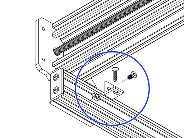
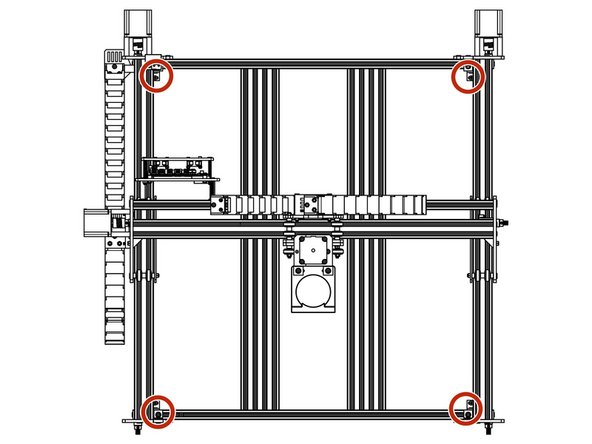
Attach one side of an Angle Corner to the inside face of the right hand C-Beam 750mm using a M5-Low-Profile-8mm bolt and a M5-Drop-In-Tee-Nut. Attach the other side to the V-Slot-2040-745mm using a M5-Low-Profile-8mm bolt and a Tee-Nut that can be inserted from the end of the V-Slot-2040-745mm.
-
Secure the Angle-Corner tightly in the corner between the C-Beam-750mm and V-Slot-2040-665mm while the machine is held square.
-
Repeat for the other 3 corner joints between the C-Beam-750mm and V-Slot 2040-745mm rails.
-
-
-
Insert 3 x Tee-Nuts into the bottom slot of the V-Slot-2040-745mm.
-
With a Universal-Bracket-Triple in hand, notice that the holes down one side are not the same distance away from the corner edge as the holes on the other side. The side with the holes closest to the corner edge should go against the V-Slot-2040-745mm.
-
With the bottom edge of the Universal-Bracket-Triple flush with the bottom of the V-Slot-2040-745mm, secure it using 3 x M5-Low-Profile-8mm’s to the Tee-nuts in Step A.
-
If you have a machine with a 750mm X-Axis, repeat this so there is 2 x Universal-L-Bracket-Triples front and back, at 209mm spacing.
-
3 x Universal-L-Bracket-Triples front and back, at 219mm spacing for a 1000mm X-Axis.
-
4 x Universal-L-Brackets front and back, at 275mm spacing for a 1500mm X-Axis.
Are you guys fitting the t-nuts to the c extrusion? you’re supposed to be fitting them to the v-slot. The ends of the v-slot are exposed so you don’t need to remove any of the end plates regardless if you read ahead or not.
Daniel Cox - Resolved on Release Reply
You will see on the bracket that on one side the holes are close to the edge and the other side run down the middle. The holes that run down the middle will go against the extrusion. I removed the plate from one end, fitted the t-nuts to the bracket and slid them from one end.
Michael Clair - Resolved on Release Reply
-
-
-
Insert 6 x Tee-Nuts into the left facing slot of the V-Slot-2040-665mm.
-
With a Universal-Bracket-Triple in hand, notice that the holes down one side are not the same distance away from the corner edge as the holes on the other side. The side with the holes closest to the corner edge should go against the V-Slot-2040-665mm.
-
With the bottom edge of the Universal-Bracket-Triple flush with the bottom of the V-Slot-2040-665mm, secure it using 3 x M5-Low-Profile-8mm’s. There should be 182mm between the Universal-Bracket-Triple and the end of the V-Slot-2040-665mm.
-
Attach another Universal-Bracket-Triple, 182mm away from the other end.
As my previous comment, I found it easier to fit the T-Nuts to the brackets ( holes that run down the centre) and then slide them into the extrusion ( edge where there is only one channel)
Michael Clair - Resolved on Release Reply
-
-
-
Insert 6 x Tee-Nuts into the furthest left bottom facing slot of the V-Slot-2080- 710mm.
-
Attach the other side of the Universal-Bracket-Triples in Step 3 along with the V-Slot 2040-665mm to the V-Slot-2080-710mm using 6 x M5-Low-Profile-8mm’s.
-
Center the V-Slot-2040-665mm on the V-Slot-2080-710mm extrusion
-
Repeat Step 3 and the above for the other V-Slot-2040-665mm and V-Slot-2080-710mm.
-
This step and previous step only need to be carried out twice for all X-Axis sizes.
I have a 750x1000 machine and I found the centre of the V-Slot 2040- 665mm to be 147.5mm (to be precise) from each end of the larger extrusion.
Michael Clair - Resolved on Release Reply
-
-
-
Through all three holes on each Universal-Bracket-Triple attached in Step 2, attach a M5-Low-Profile-8mm bolt with a slightly screwed M5-Drop-In-Tee-Nut on the end.
-
Bring the Spoiler-Board-Support-Assemblies down onto the central two sets of Universal-Bracket-Triples aligning the M5-Drop-In-Tee-Nuts with the slots. Tighten the M5- Low-Profile-8mm’s to secure the Spoiler-Board-Support-Assemblies.
-
If you have an X-Axis with a 750mm X-Axis, the assemblies in Steps 3 and 4 will take up all Universal-L-Bracket-Triple sets.
-
For a 1000mm X-Axis there will be one set left empty, attach the left over V-Slot-2080 to this set.
-
For a 1500mm X-Axis there will be two outer sets left empty, attach the two left over V-Slot-2080’s to these sets.
Found this difficult. Raise the machine up so you can get your head under to sight the bolts. Found it easiest after fitting the tee nuts to line them up then push the bolts upward to receive the spoiler support then drop the spoiler support onto the tee nuts whilst still pushing them up, let the spoiler drop flush with the rest of the frame. Then holding the bolts in place tighten them one by one. Hope this helps and makes sense.
Daniel Cox - Resolved on Release Reply
-
-
-
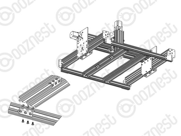
Make sure your WorkBee CNC Machine is placed on a flat and level surface.
-
The Screws referenced in this step are not provided.
-
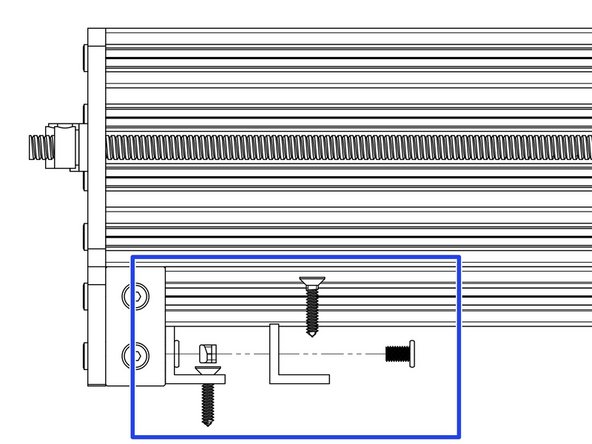
Insert 1 x Drop in Tee-Nuts into the bottom slot of the V-Slot-2040-745mm.
-
With a Universal-Bracket-Single in hand, notice that the hole down one side is not the same distance away from the corner edge as the hole on the other side. The side with the hole closest to the corner edge should go against the V-Slot-2040-745mm, 50mm away from the End-Cap.
-
With the bottom edge of the Universal-Bracket-Single flush with the V-Slot-2040-745mm, secure it using 1 x M5-Low-Profile-8mm’s and the Drop in Tee-nut inserted previously.
-
The Universal-Bracket-Single can now be secured to your table using a general purpose wood screw.
-
Repeat for the other three corners.
-


Thanks for following the guide. Any issues, please contact us!
Thanks for following the guide. Any issues, please contact us!
Cancel: I did not complete this guide.
34 other people completed this guide.

2 Comments
I think the instructions are correct - “…closest to the corner edge…” not the edge edge (IYKNWIM). In other words the holes closest to the angle of the bracket go against the V-Slot-2040-745mm.
Steve Johnston - Resolved on Release Reply
Step 2: The picture is correct, not the instructions.
Instructions say: “The side with the holes closest to the corner edge should go against the V-Slot-2040-745mm.”
Picture shows: The side with the holes closest to the corner edge NOT going against the V-Slot-2040-745mm.
Michael Zucker - Resolved on Release Reply
thanks for the tip paul, made it easy.
Daniel Cox - Resolved on Release Reply
Applying the t-nuts in previous steps would have been easier. Though this step isn’t difficult if done right… Put both bolts through the angle block and screw the ‘Drop-in’ t-nuts onto each bolt (couple of threads only) whilst in your hand before bringing the angle to the extrusions. Then place each t-nut in the v of the two extrusions and tighten. The t-nuts will twist and lock-in as you tighten, you don’t have to try and turn the t-nuts on their own within the extrusions and then screw in if that makes sense.
Paul Rutt - Resolved on Release Reply
Indeed, you can't get T-nuts in without removing the end-caps fitted in the previous step!
Alex Forrester - Resolved on Release Reply
Yeah, and we just put on the end plates in the previous step, so not even the T-Nut mentioned here can be inserted from the end without removing the end plates.
Björn - Resolved on Release Reply
Hi Oscar, Thank you for your feedback, we will take it on board! Ryan
Ryan Lock - Resolved on Release Reply
Imo drop t-nuts should be substituted by t-nuts slides into the rails on previous page. Too much time consuming.
Oscar - Resolved on Release Reply