
-
-
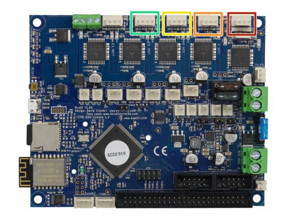
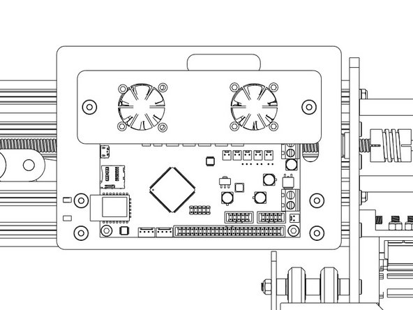
Making sure the board is orientated in the correct way as displayed in the image.
-
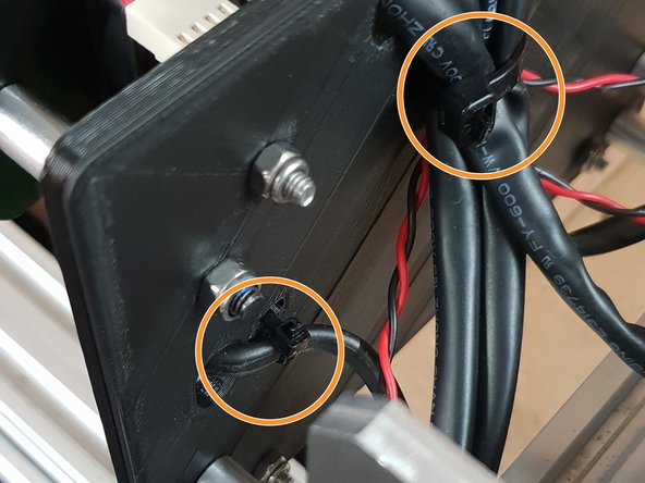
The Large Cable Tie highlighted in Orange is for the 4 Stepper Motor Cables and the Limit Switches.
-
The Small Cable Tie highlighted in Red is for the power cable.
-
The Small Cable Tie highlighted in Yellow is only needed if you have the Ethernet Version, and is to secure the Ethernet Cable.
-
-
-
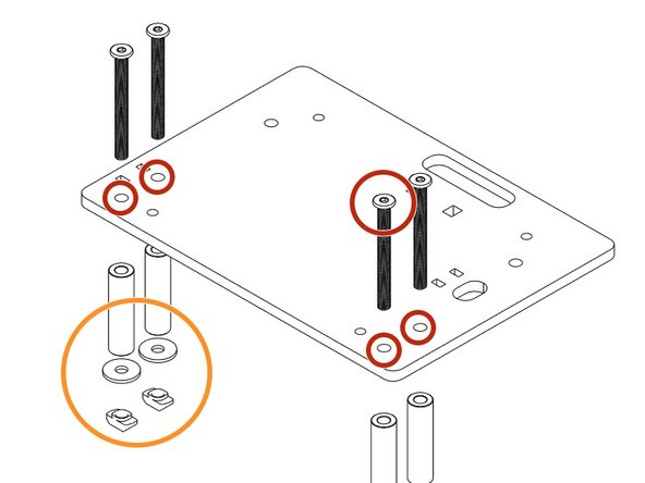
Insert a M4 Cap Head Bolt 20mm through each hole on all 4 corners on the Duet 3D Controller.
-
Onto each bolt slide a 1/4" Nylon Spacer.
-
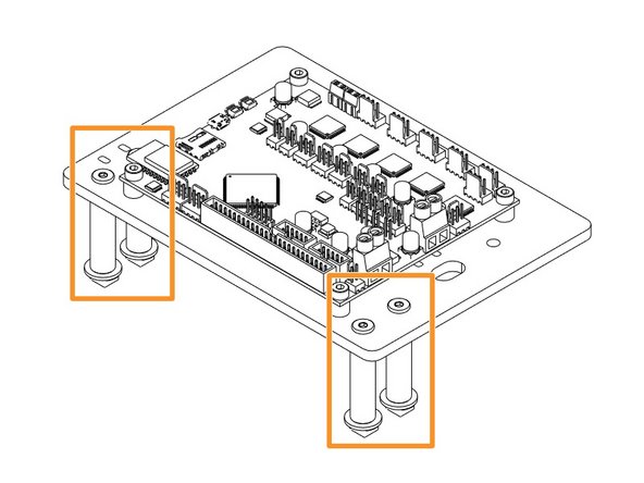
Now it is time to join the Duet to the Duet Mount. Insert the bolts into the holes on the Duet Mount and secure using 4 x M4 Nyloc Nuts.
-
-
-
Insert 4 x 50mm M5 Low Profile Bolts through the holes indicated in the image.
-
Place a 1-1/2" Aluminium Spacers over each bolt followed by a Slot Washer and finally a M5 Drop in Tee Nut.
-
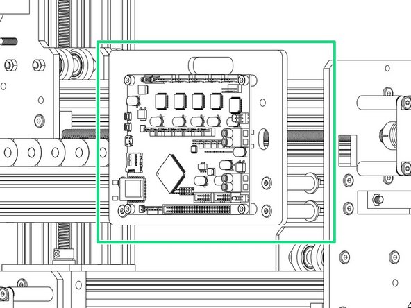
Once assembled line up with the 2040 Extrusion on the right-hand side of the machine looking from the back and fix into place tightening the M5 Bolts until the Tee Nuts engage
-
-
-
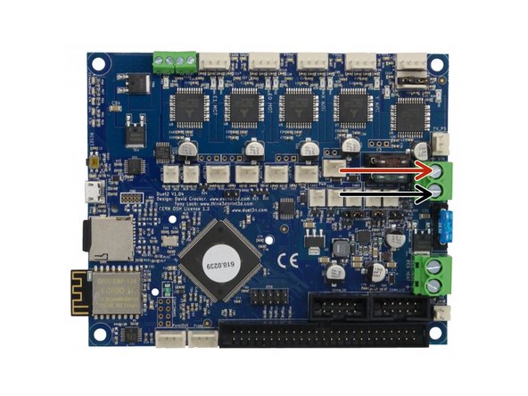
The Mains Power should remain off during all wiring of the Duet Controller.
-
PSU Cable from Power Supply - Connect Red Positive Wire into the Top Screw Terminal and Black into Bottom Screw Terminal.
Don’t forget to feed the wire through the cable tie you inserted earlier
david.birch@essex.ac.uk - Resolved on Release Reply
-
-
-
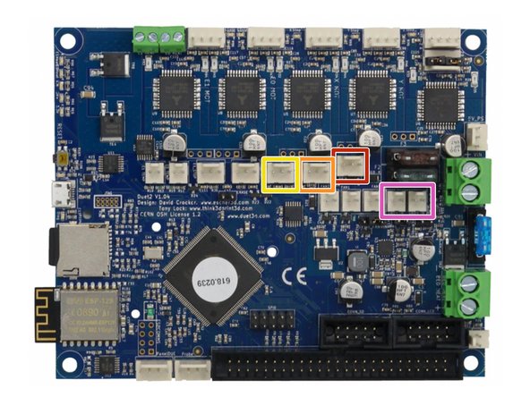
The connectors for the Duet controller are keyed, so there is only one way which they can plug in.
-
Z-Axis Stepper Motor Wire.
-
Left Y-Axis Stepper Motor Wire.
-
X-Axis Stepper Motor Wire.
-
Right Y-Axis Stepper Motor Wire.
run the cables through the slots on the PCB backing 3D print first before plugging in?
Gwilym Davies - Resolved on Release Reply
-
-
-
Z-Axis Limit Switch
-
Y-Axis Limit Switch
-
X-Axis Limit Switch
-
Fans connected to either of the Always on Fan Terminals.
-
-
-
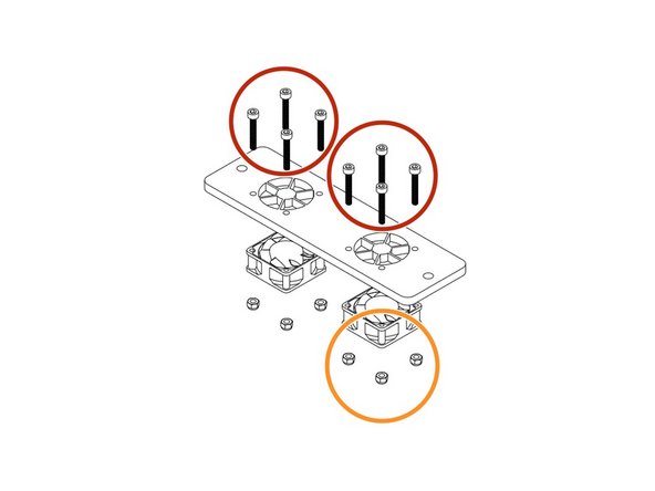
Use 8 x M3 Cap Head 20mms to fix the fans highlighted in Yellow onto the Mount with the Fan label facing outward.
-
Secure the M3 Cap Head 20mm's using 8 x M3 Nyloc Nuts.
-
Thread 2 x M5 55mm Low Profile Bolts through the fan mount.
-
Slide the Aluminium-Spacers-1-1/2" over the bolts.
-
Now attach to the Main Board mount using 2 x M5 Nyloc Nuts.
-
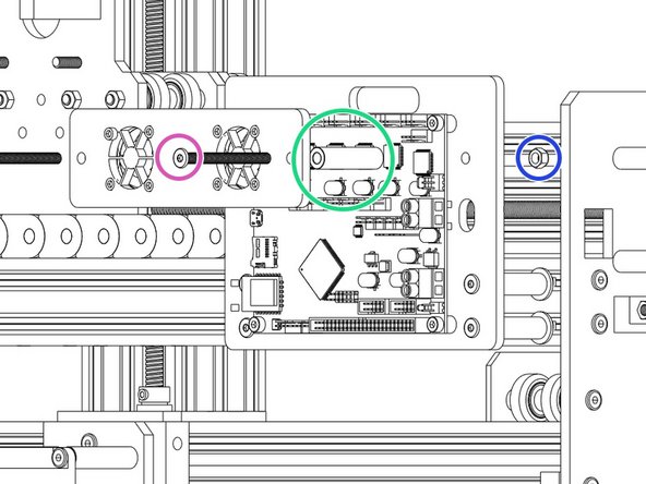
Remember to connect the fans to Always on Fan connection of your Duet Controller before tightening the M5 Nyloc Nuts.
I fitted 2 precision shims to each screw to move it away from the brown fuse
Michael Clair - Resolved on Release Reply
just realised, they’re marked in the previous step, in pink
Gwilym Davies - Resolved on Release Reply
Also, where is that ‘Always On’ fan connection?
Also, the bottom right bolt and nut gently touch the brown fuse on the board. This doesn’t look right, have I got it wrong?
Gwilym Davies - Resolved on Release Reply
-
-
-
Using the already inserted cable ties fix the wires into place securely to prevent any unnecessary movement and to keep the machine looking neat!
-
If you have the Ethernet version also secure that.
Hi @danny this is mentioned in the Beginning of the Electronics Assembly “If you have the Ethernet version of the Duet, now would be a good time to also insert this wire.” - 1. Y-Axis Drag Chain Assembly
Hope this helps!
Ryan Christy - Resolved on Release Reply
The routing of the ethernet cable should have been brought up when the Y-Cable chain was filled with wires. This is so hard to add to the mix now.
Adam J Barnett - Resolved on Release Reply
where should we run the ethernet cable? Also through the cable chain, but then where?
Gwilym Davies - Resolved on Release Reply
See the yellow dot in “Step 1 Fixing the Cable Ties into position”, there is a hole and tie for the ethernet cable.
Björn -
-


Thanks for following the guide. Any issues, please contact us!
Thanks for following the guide. Any issues, please contact us!
Cancel: I did not complete this guide.
38 other people completed this guide.

2 Comments
the Z sense needs to be plugged in now to as access with the fans on is limited
Pete Franklin - Resolved on Release Reply
No mention of Bolt size on step 3. I used the 50mm ones…
Simon Stockdale - Resolved on Release Reply