
-
-
Attach 2 x ACME-Nut-Blocks to one of the Y-Plates using 4 x M5-Low-Profile-25mm bolts & 4 x M5-Nyloc-Nuts. On each bolt, in-between the ACME-Nut-Block and Y-Plate, there should be an Aluminium-Spacer-3mm and a Precision-Shim. Only loosely tighten these bolts so the ACME-Nut-Blocks can still move side to side.
-
Thread a Y-ACME-Lead-Screw through both ACME-Nut-Blocks. Tighten the bolts holding one of the ACME-Nut-Blocks, making sure it is square to the Y-Plate.
-
To remove any backlash, pinch the loose ACME-Nut-Block towards the previous one, and tighten the bolts holding it. Leave the Y-ACME-Lead-Screw threaded through the ACME-Nut-Blocks.
-
-
-
First attach the bottom right wheel set; insert a M5-Low-Profile-60mm bolt through the Y-Plate-Assembly from the back. On to this bolt, add an Eccentric-Spacer-6mm, Precision-Shim, Solid-V-Wheel-Xtreme-Assembly, Aluminium Spacer-9mm, Solid-V-Wheel-Xtreme-Assembly, Precision Shim, and a Eccentric-Spacer-6mm in this order.
-
Next, add a Y-Plate-Inner onto the top of this assemblage, and then slightly thread on a M5-Nyloc-Nut. The rounded portion of the Eccentric-Spacer-6mm should be inserted into the hole on either the Y-Plate-Assembly or Y-Plate-Inner (depending on which side it is on).
-
Repeat for the other wheel set on the bottom row corner.
-
Repeat for the 2 wheel sets on the top row, however for these sets use Aluminium-Spacer-6mms instead of Eccentric-Spacer-6mms.
-
Once all of the wheels are attached the M5-Nyloc-Nuts can be tightened down. Ensure that the Solid-V-Xtreme-Wheels can still rotate freely. On the hexagonal portion of the Eccentric-Spacer-6mm, there will be one face that is marked with ‘6mm’.
-
Using a spanner, adjust each Eccentric-Spacer-6mm so that this face is facing downwards. Doing this maximizes the gap between the top and bottom row of wheels.
-
-
-
Run any piece of C-Beam extrusion in-between the two rows of wheels. Initially, there may be a small amount of play between the C-Beam and wheels. Turn the assembly upside down so the C-Beam is sitting on the row of wheels with the Aluminium-Spacer-6mms.
-
Starting with one pair of wheels, adjust both Eccentric-Spacer-6mms down onto the C-Beam Extrusion until there is a small amount of friction between both wheels and the C-Beam Extrusion.
-
When adjusting the pair of Eccentric-Spacer-6mms ideally they should be adjusted identically. However, sometimes one will need to be adjusted slightly more than the other to get both wheels engaged with the C-Beam extrusion.
-
Repeat for the other pair of wheels with eccentric spacers.
-
Slide the C-Beam extrusion back and forth through the wheels. This should require a small amount of force, and all wheels should spin as it rolls. Also check there is no wobbling of the extrusion. Once happy, double check the tightness of the M5-Nyloc Nuts.
O.K. Tried to delete my previous, it won’t go away.
Although it’s a good idea to lay all the parts out so you can see them all, it’s not usually possible, I’m sure. I didn’t, which is why I didn’t spot the actual “C” beams, looked for all the worls as all the sections were identical. They’re not. Dhuh!
Found ‘em, & all is good. One point, the precision shims in two different packets are slightly different in thickness, but only by around 0.2mm, so I used all the same for the assembly.
SFSG (So Far So Good).
RYAN - If you get a chance, please try to fix the DELETE comment button, so I can tidy up this thread for future users.
Would also like the ability to post an image for the same purpose.
Pablo Verity - Resolved on Release Reply
Part 2. Run C beam through? A 20x40 beam tends to be sloppy when on it's own. Umm. Power on.
Pablo Verity - Resolved on Release Reply
Trying to clarify, won’t let me edit my pervious.
So, Step1 is make the wheels up. Fine.
Step 2 is make the Y plates. Fine.
Use any C beam to check the tension of the wheels? Really? How is that possible? It would only be possible if the beams were assembled. So they’d have end plates on. So the Y assembly would have to be slid on first, then the plate to keep the two C beams would be fitted. So that throws out all the “just follow the guide”… I’m not going to have any problems, but it is less than clear for anyone who would find this daunting to start with… Just sayin’.
If I find anyway to help, I’ll kill this post, & put up what I feel would. Keep safe, y’all!
-
-
-
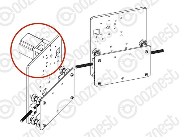
Repeat the this section for other Y-Plate. As seen it should be a mirror image of the previous assembly.
-
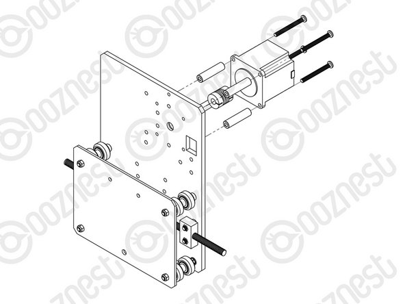
A NEMA23-Stepper-Motor needs to be attached to the second Y-Plate Assembly. See pictures 2 & 3.
-
Slide the 1/4” side (the side with the smallest hole) of the Flexible-Coupler onto the shaft of the NEMA23-Stepper-Motor. Don’t tighten it down at this point.
-
Attach the NEMA23-Stepper-Motor to the threaded holes on the Y-Plate using 4 x M5-Low-Profile-50mm bolts and 4 x Aluminium-Spacer-40mm’s.
-
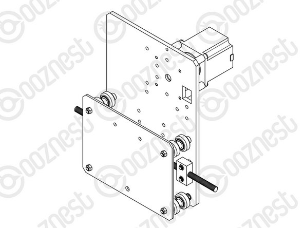
Orient the NEMA23-Stepper-Motor so that the wire is towards the back of the Y-Plate (the side closet to the small rectangle opening).
-
The Y-Plate Assembly with the NEMA23-Stepper-Motor will be known going forward as the Y-Plate-Left Assembly.
-
The other Y-Plate Assembly (Without the NEMA23-Stepper-Motor) will be known going forward as the Y-Plate-Right Assembly.
The 4 x Aluminium-Spacers-40mm’s should be 50mm long, instead of only 40mm. Later on (4. X-Gantry Assembly, step 3), to insert the bearing, an 8mm-Shim and the 8mm Lock collar, the flexible coupler is pushed so far into the motor shaft, that the flexible part is completely over the motor shaft. The lead screw already has enough length to accommodate these extra 10mm, so I leave this suggestion for an improvement.
Luis Jorge - Resolved on Release Reply
-


Thanks for following the guide. Any issues, please contact us!
Thanks for following the guide. Any issues, please contact us!
Cancel: I did not complete this guide.
63 other people completed this guide.

8 Comments
Am I the only person who doesn’t understand step 3? the picture doesn’t seem to have anything to do with the instructions, would be nice to have a diagram.
Daniel Cox - Resolved on Release Reply
Pro tip - the stick of the supplied lollypop can be used to move the washer within each wheel so that it the bolt goes through. I assume that’s why its enclosed ;)
Would recommend assembling both of these plates at the same time - lay them down flat on the table as shown in the first figure of step 4 - with the two rectangular holes close together. Follow the instructions for the right hand plate and mirror for the left hand plate (which will be the one you add the motor to).
david.birch@essex.ac.uk - Resolved on Release Reply
I would have loved to ahve seen a list of all tools required in the very first part of the guide.
That said these instructions were extremely easy to follow.
Lee Wright - Resolved on Release Reply
I’d love it if this forum had delete & edit buttons that worked! Could get a bit useless, quickly, otherwise..
Pablo Verity - Resolved on Release Reply
These guides should have a list of required tools and sizes. Is that posted somewhere and I’m missing it?
Adam J Barnett - Resolved on Release Reply
I agree, a cheap 6mm spanner would have been great. I think it is good that not all tools are provided, like with some kits, since most often you already have the required tools, and including them is a waste of resources. A 6mm spanner is probably quite uncommon to have, and an adjustable spanner does not fit. Although not optimal, I was able to use pliers.
many thanks Robert so i take it Robert this is the latest version? with the link you provided?
sales@badgerandbowl.com - Resolved on Release Reply
Hi, the one I linked is the latest version which is applicable to your machine.
Robert -
I have commented on further instru tions about the nut blocks each time it mentions 3mm spacers I don't have these in my packages only 9mm and 6mm no 3mm spacers, can someone clear this up for me before I build any futher.
Regards merv
Instructions below as per listed
On each bolt, in-between the ACME-Nut-Block and Y-Plate, there should be an Aluminium-Spacer-3mm and a Precision-Shim….???????
sales@badgerandbowl.com - Resolved on Release Reply
Hi Merv,
I have checked your order, and you have the WorkBee Z1+, this is the incorrect manual to be following. Please follow the manuals on this page: Original WorkBee Z1+ Assembly Manual - V1.0
That will solve your issue, as the assembly is different.
Thanks
Robert -
Crikey, I seldom post anything anywhere, 3 in short succession on one topic, sorry. The ACME block has counter bores that are only just smaller than the spacers. Why not modify the block to omit the counter bore to add stability as it seems to be otherwise surplus and why not have just one spacer instead of 2?
koenigshaus - Resolved on Release Reply
Also, why have your Name displayed when you post and not the @Username ?
koenigshaus - Resolved on Release Reply
I’m 10 mins into this build and already thinking it’s nothing like Lego or perhaps the Prusa MK3s that I’ve just built. Why not have numbered boxes that tally with the current instruction and why not have a “shopping list” at the start so you can gather the required parts for that step. It’s sooooooo long winded to have to read the step to try and guess which box a part might be in. Apologies if I’ve missed something but from my POV plenty of room for improvement. Ages ago I thought about creating an assembly YouTube but assumed the distructions would be awesome so didn’t bother, might actually do that so others can have a much easier time.
koenigshaus - Resolved on Release Reply
Ryan has come back on this and the switch to exterior bearing and recess is for performance reasons, so can’t be skipped for conversion. Not what I wanted to hear, but there you go looks like Im disassembling pretty much the whole thing :)
max - Resolved on Release Reply
I have a machine I built last year with version 1 of the manual and am now converting to screw drive on the Y axis. I noticed in version 2 of the manual they switched the bearing and recess to the outside of the y plate where to motor is. In version 1, the bearing and recess are on the side of the wheels. Also in version 2.0 they specifically highlight the recess, whereas in version 2.1 they don/t
I can’t see this making any difference in performance. I’ve asked support to advise before i continue with conversion as I really hope I can just keep the bearing on the inside like it is currently. Otherwise I’d have to disassemble the whole machine basically which id rather avoid.
max - Resolved on Release Reply
I have just built my WorkBee V2.1, and I didn’t have this problem with the Y plates being handed. They were both identical.
Jonathan Pearce - Resolved on Release Reply
Also in the larger versions there are more wheels to add which aren’t mentioned in where, 6 in total each side
Scott Rotton - Resolved on Release Reply
OMG i just got half way through the build and found the is a left an right plate also, not mentioned and cost me literally hours or time, super annoy this instructions are bad
The difference is the larger hole next to the top where the square hole is is slight recessed, the larger part of the whole should be facing outwards away from the spindle area, it is used to hold a bearing in place later down the track to stop the lead screw hitting the frame, its extremely difficult to see from the pictures and should be highlighted in red for future revisions
If you get this wrong you will find in step 4 you have to start again pretty much, in step 4,3 you can see the image clearly where the bearing needs to slot in
Scott Rotton - Resolved on Release Reply
Note to anyone else building this, don’t attach the nut blocks to one of the y plates as stated! There is a left and right plate..! Found this the hard way! by the square cut out there is a 10mm round hole one side and a larger one the other side set into the plate this needs to be on the outside! (Larger hole) for the bearing to sit into later! Found this out once I got to the y axis assembly! Had to completely dismantle it! Not clear at all!! Not impressed! Nor are these instructions for the upgrade of a 1500x1500 belt to screw drive loads of parts not shown!
waste of time stripping down rebuilding And now having to strip down again!
Darren clark - Resolved on Release Reply
I wonder if Darren was assembling another kit, as I followed the instructions to the point and had no issue. I carefully examined both plates and they are identical. The other one just has to be assembled mirrored (as stated in the manual).
Björn -