
-
-
You are going to need our Motor Wire and Limit Switch Cheat Sheet. We recommend printing it off!
-
-
-
Look at the X & Y Drag-Chains.
-
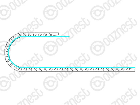
On each end, there is an end mount.
-
If the end mount connects to the next link on the outside, this is known as the Moving End.
-
If the end mount connects to the next link on the inside, this is known as the Fixed End.
-
It is important you remember this, as these terms will be used going forward.
-
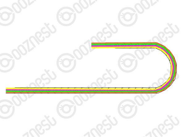
Take a look at the links of the Drag-Chains. On one side of each link, there is a little slot.
-
If you put a Flathead Screwdriver in this slot and twist. The top tab of the Drag-Chain will open.
-
Knowing this can come in useful later!
One drag chain is six links longer than the other which is X and which is Y ?
Colin Eaton - Resolved on Release Reply
-
-
-
Lay the Drag-Chain-Y flat out on a table.
-
Feed through Limit-Switch-1.
-
The switch end of Limit-Switch-1 should be at the Fixed End of Drag-Chain-Y
-
Feed through the output cable of the Emergency-Stop.
-
The red/black crimped connectors should be at the Moving End of Drag-Chain-Y.
-
Feed through Motor-Wire-4 and Motor-Wire-5.
-
The black connector of the Motor-Wires should be at the Fixed End of Drag-Chain-Y.
-
If you have the Ethernet version of the machine. Feed through the Ethernet Cable. (Orientation does not matter)
I've built my Workbee Z1 + with no issues, the wiring on the other hand is confusing to say the least. I'm really struggling. I can't find an easy this goes there guide on the Ooznest diagrams, can anyone please help me so I can get off the ground and learning my new machine.
Hi Paul,
It looks like you have contacted us directly through our help page on the website. We will help you via that channel.
Thanks.
I’ve popped all the little lids on the drag chain open and laid all the cable inside them back together. It took a tiny bit of time to open each one but it meant that I could lay more flat not tangled and no risk of damaging the connectors well worth the time I thought.
nige kearney - Resolved on Release Reply
Like Emil (above), I put a thin length of fishing rod through the drag chain and taped the wires to it and then SLOWLY pulled them through…
Ivan Flack - Resolved on Release Reply
I gathered all the cables together so that had three white connectors and the black and red cable end points (essentially everything that will go into the Duet) and pushed them through en-masse. The collection seems to hold together well and I got 99% of the way before I had to just fish a couple through, once through I pulled them through some distance.
might be useful if there was an idea of how much ethernet cable is required to run through the drag chain and up to the controller, you’d then be able to estimate how much you’d need to get it to where your PC is going to be and buy an appropriate length in advance… or a bit of guidance about how to run it outside of the drag chain…
Neil Dilly - Resolved on Release Reply
For motor wires 4&5, which way round do they feed through? Should the white or black connectors be at the fixed end?
I’m sure this must be obvious, but I can’t work it out.
Cheers,
Stewart
Can any of the inner cross sections of the drag chains be temporarily removed to help with feeding wires through because the previously wound wires are catching on every single thing they can catch on and are starting to become a complete joke
Thomas Easton - Resolved on Release Reply
Hi Thomas,
Thanks for your comment. The tabs on the drag chains can be flipped open with a small flat head screw driver. This allows for easier access.
Robert
Robert -
Hint: If you have the Ethernet version:
You may need to consider leaving the Ethernet cable outside the drag chain. Why? Because the plug side where you fix to your laptop will be at the fixed side of the drag chain , which will be at the left back side of the machine (far inside). Personally I took it out of the drag chain, kept it free.
Mohammed M - Resolved on Release Reply
I too had this question. The cable end with the crimped black and red cores should come out of the moving end (the end thats going to be attached to the y carriage/controller)
-
-
-
Position Drag-Chain-Y flat along the left side of the machine.
-
The Fixed End of Drag-Chain-Y should be at the back of the machine.
-
The Fixed End of Drag-Chain-Y will be fixed into position in a later guide.
-
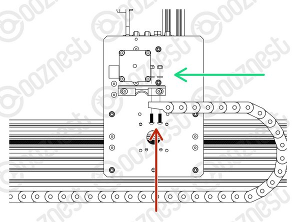
Bring the Moving End of Drag-Chain-Y upwards to the Drag-Chain-Mount on the Y-Carriage-Left.
-
Attach it to the 3 holes on the Drag-Chain-Mount using 3 x M5-Button-Head-Bolt-16mm through the bottom.
-
The add 3 x Precision-Shims and 3 x M5-Nyloc-Nuts on the opposite side of the Drag-Chain-Mount.
The single nut at the “front” of the moving end is very difficult to get on without taking the stepper motor bolt and spacer off.
I just cut 2mm of the front M5 bolt and it didn’t touch the stepper motor spacer anymore!
Ivan Flack - Resolved on Release Reply
To get the single nut tightened we had to take two spacers off the stepper motor.
Chris McMahon - Resolved on Release Reply
I suggest clarifying here that the fixed end of drag chain Y will be handled at the final assembly. It should be kept on the side for now. Coz I kept scratching my head until I reached the final assembly and found it there.
Mohammed M - Resolved on Release Reply
-
-
-
Lay the Drag-Chain-X flat out on a table.
-
Feed through Motor-Wire-6
-
The black connector of Motor-Wire-6 should be at the Moving End of Drag-Chain-X.
Pull the Z limit switch and touch probe wires through now or pull a second string the chain for the coming steps.
Jacob Weiand - Resolved on Release Reply
Lost a number of the M5 16mm bolts due to poor thread. I’ve now got two stuck in the drag chain, as soon as they started to bind I tried to remove them and the heads have stripped. I think there might be an issue with these bolts as I’ve got 6 failed so far, these two are going to have to be cut off. Word to the next builder coming along if these tighten even a little bit, remove and discard.
Tim Wiseman - Resolved on Release Reply
I’ve had a few dodgy bolts and nuts so far, I do hope there are still enough to complete the build.
Hi Tim,
My apologies for this, if you need any replacing, just get in contact here and we can sort it out: https://ooznest.co.uk/help/
Robert -
-
-
-
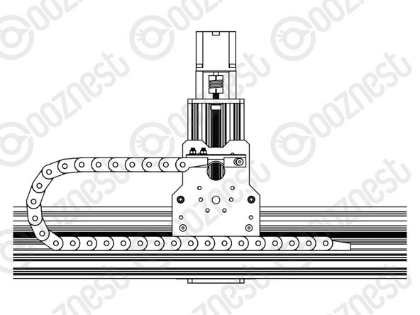
Position Drag-Chain-X flat along the back of the X-Gantry sitting on top of Extrusion-B.
-
If looking from the back, the Fixed End of Drag-Chain-X should be at the right side of the machine.
-
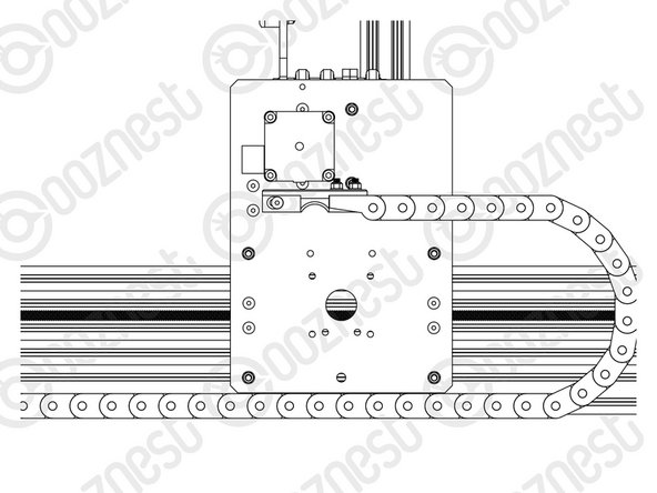
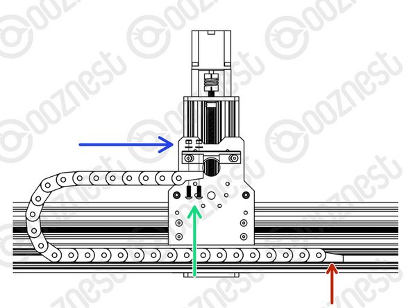
Bring the Moving End of Drag-Chain-X upwards to the Drag-Chain-Mount on the X-Carriage.
-
Attach it to the 3 holes on the Drag-Chain-Mount using 3 x M5-Button-Head-Bolt-16mm through the bottom.
-
The add 3 x Precision-Shims and 3 x M5-Nyloc-Nuts on the opposite side of the Drag-Chain-Mount.
-
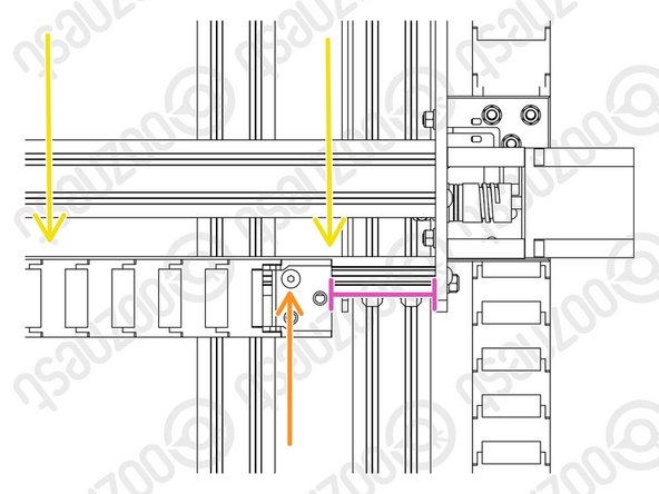
Attach the Fixed-End of Drag-Chain-X to Extrusion-B using 1 x M5-Button-Head-Bolt-8mm and a M5-Drop-In-Tee-Nut.
-
There should be a 90mm gap between the end of Drag-Chain-X and the inside of the Y-Carriage. You can reduce this distance once you start using the machine to stop Drag-Chain-X from hitting the Y-Carriage at the opposite end.
-
Drag-Chain-X should run flush with Extrusion-B.
With the 90mm gap as described on a 1500mm machine, i found the drag chain coil ran hard into the right y carriage well before the x limit switch is triggered. I reduced the gap to 65mm and it clears it now.
-
-
-
Don't worry we will tidy up all the messy wires!
-
Guide Complete - Proceed to 2. Limit Switches
-


Thanks for following the guide. Any issues, please contact us!
Thanks for following the guide. Any issues, please contact us!
Cancel: I did not complete this guide.
62 other people completed this guide.

10 Comments
Hi Ryan, on Step 4, I had to swap an M5x16 bolt for an M5x12 bolt to avoid a foul with one of the Stepper Motor spacers.
Ian Martin - Resolved on Release Reply
Hi Ian,
Thanks for your feedback. That is strange, on our machine here it misses it by 1mm. I think there is some movement on the spacer to sit slightly higher. Robert
Robert -
I have a problem where the Drag-Chain-X is too long (so collides at 90mm offset etc) and my Limit switch-2 which runs inside is too short and only just protrudes?
Mark Stone - Resolved on Release Reply
Hi Mark,
Thanks for your comment. You can move the Fixed end of the Drag Closer to the Y-Plate, I wouldn’t go no closer than 45mm, to leave room for the controller
Robert -
Which is the longest wire 5 or 6 as my clips come off and I’m not certain I’ve got them the right way round
Rob Thompson - Resolved on Release Reply
I think step 5 is wrong or somewhat misleading as it mentions drag chain y? I ended up with the cable the wrong way round for the x when reading this.
Step 5 Drag-Chain-X
Feed through Motor-Wire-6
The black connector of Motor-Wire-6 should be at the Fixed End of Drag-Chain-Y.