
Introduction
Please read before proceeding to avoid damaging the controller and voiding your warranty
- Avoid connecting the Controller via USB when you do not need to. (Except when instructed to in the guides)
- Always unplug the WorkBee Power Supply before connecting the USB Cable.
-
-
The Emergency Stop has been pre-tested by Ooznest. But you should test it again.
-
First insure the machine is switched on, and have WorkBee Control open on your web browser.
-
Press the Emergency Stop.
-
You should loose connection to WorkBee Control.
-
If you do not loose connection make sure the USB Cable is not plugged in.
-
If you still do not loose connection, stop here and Contact Us.
-
With the connection lost, unlatch the Emergency Stop.
-
After a few seconds WorkBee Control should reconnect.
-
-
-
If looking at the machine from the front the axis motion is:
-
The X-Axis is positive towards the right.
-
The Y-Axis is positive towards the back.
-
The Z-Axis is positive going up.
-
-
-
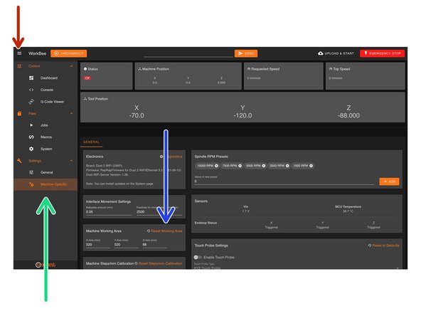
In WorkBee Control open the Navigation Menu
-
Under 'Settings', press 'Machine Specific'
-
Under the Panel called 'Machine Working Area' press 'Reset Working Area'
-
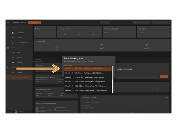
Under the 'WorkBee Model' dropdown select your machine size.
-
Yours is a Z1+ Model
-
Confirm by pressing 'Yes'
-
The machine is now configured. No restart required.
Hi Paul,
Workbee Control is built into the Duet2 Controller, you would need to connect to it by following the Ethernet guide here - 1. Connecting your Controller to a Network - Ethernet
Thanks.
-
-
-
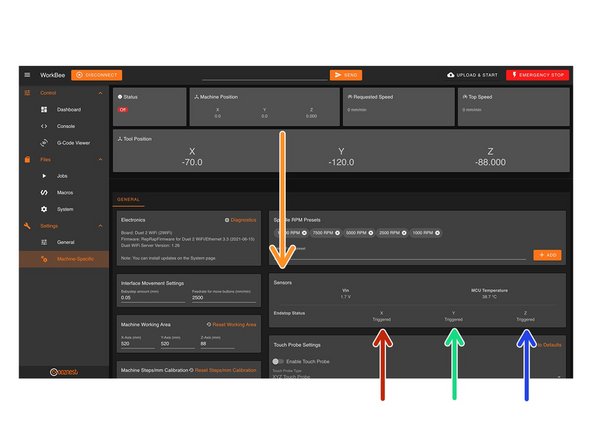
On the same page, under the Panel called 'Sensors' we can test the Limit Switches.
-
Activate the X-Axis limit switch with your finger and hold.
-
The Endstop Status should change to 'Triggered'
-
It is normal for there to be a delay between pressing the limit switch and the status being updated. Please do not be concerned, the board will stop the motor instantaneously.
-
Repeat this procedure for the Y-Axis Limit Switch.
-
Repeat this procedure for the Z-Axis Limit Switch.
-
If any do not behave as intended do not proceed with this guide, please Contact Us.
If you have the XYZ touch probe, now is a good time to test it. I bought the z1+ and the probe was not enable by default. I had to go into Settings, then Machine Specific and enable the touch probe. From there I clicked on "Reset to Defaults" to ensure the defaut settings were in place for the prove. I ran into trouble at a later stage trying to get this enabled as it is in some documentation but not others
Dylan Feeney - Resolved on Release Reply
Hello,
the Z-Axis Limit Switch have the status “triggerd” while it is obviosly not triggered.
Hubertus Schulte-Nölke - Resolved on Release Reply
Hi Hubertus,
Have you confirmed they are wired into the correct ports. If the Z-Axis is plugged into the wrong port, it would always stay triggered.
Robert -
-
-
-
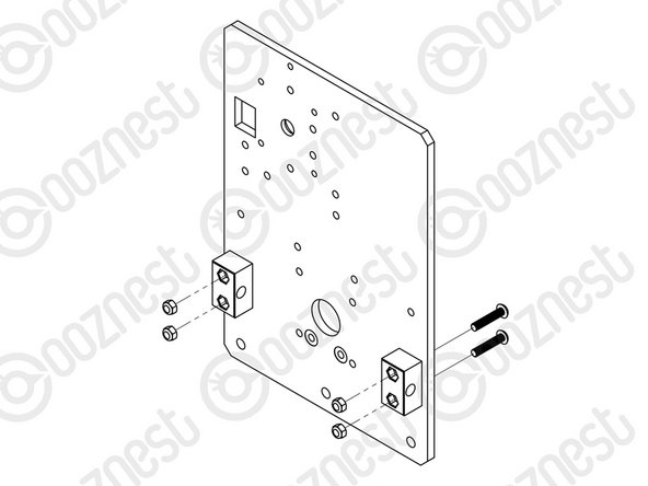
At this point in time, the Nut Blocks on X & Y-Axis Carriages should be loose.
-
Tighten these.
-
Do not over tighten them, they will need to be undone shortly.
-
-
-
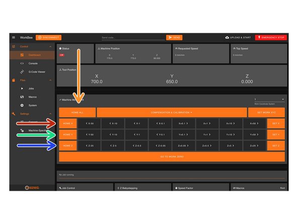
When the machine homes, it will raise the Z-Axis, and then move the X and Y-Axis to the far right-hand corner.
-
If any of the points below do not behave as explained do not proceed with this guide, please Contact Us.
-
Press Home Z. The Z-Axis should raise upwards, bounce once on the limit switch, and then stop.
-
Press Home X. The Z-Axis should home like the previous. The X-Axis should then move towards the right, bounce once on the limit switch, and then stop.
-
Press Home Y. The Z-Axis should home like previous. The Y-Axis should then move towards the back, bounce once on the limit switch, and then stop.
-
Press Home All. The Z-Axis should home like previous. Then the X and Y-Axis should home like previous.
Is it normal for the home speed to be very fast also the Y axis home sound terrible and is inconsistent as if its not sure which way to go
chris jones - Open Reply
Hi Chris,
That sounds strange. The fast speed and rough Y-axis noise could point to a wiring, limit switch, or firmware setup issue. Please reach out to our technical support team and we’ll help you diagnose it properly. https://ooznest.co.uk/help/
Cyndy -
Hi, midway through this test I got an an heat warning and noticed the fans were not working. I hot the wmergency stop and about to open the control box to check connection when a single fan automatically turned on. But only one, not both. Thoughts?
Tim Pardoe - Resolved on Release Reply
Hi Tim,
Can you loosen the bolts that hold the fan to the case, then give the fans a manual push. Sometimes if the bolts are done up too tight this can pinch the fans and stop them spinning.
Thanks.
-
-
-
Home the machine and use the jog buttons to move the machine roughly into the middle of the working area in X & Y.
-
Leave the machine powered on so the Stepper-Motors stay locked.
-
If at any point in Step 7, 8 or 9 you loose power to motors and need to re-lock the motors, go to Control > Console and send the command 'M17'
-
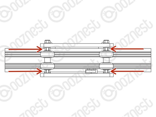
Loosen all the Nut-Blocks on the X & Y-Carriages.
-
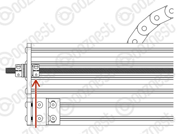
Loosen the Clamping-Collars that are on the inside channel of Extrusion-E/F on the X & Y Axes.
-
Move the Rubber-Bushings & Clamping-Collars away from the plates.
The instructions are little ambiguous at step 7:
1. the wording says to loosen the clamping collars and move the rubber bushing. But the diagram and all the comments also show/comment on loosening the flanged-bearing. The instructions and diagrams should not contradict each other
2. It is also ambiguous whether to do the above at both ends of the three lead lead screws or just at the tensioning ends only (i.e. whether it is necessary to loosen everything at the stepper motor ends of the lead screws ?? Loosening the stepper motor end on the X axis is particularly difficult because of the wiring harness at the controller
Phil Scoltock - Open Reply
1) Thank you, the main point is just to make all the locking components loose on the side where you'd be tensioning - so as not to constrain the leadscrew at the collar while tensioning
That would just apply force against the collars directly and not apply tenstion into the leadscrew. With both loose, you can apply tension (leadscrew pulls against far plate) then tighten outside collar to lock the tension in, then tighten inside collar with rubber bush with some force to constrain the leadscrew in both directions
At step 7 we loosen the inside collar, and at step 8 (after threading on the tensioning knob) we loosen the outside collar. Then at Step 8 we tighten outside collar first (2nd green bullet point). Finally at Step 9 we reposition the inside collar.
The steps are actually correct, and if not done in this order can make tensioning difficult.
2. Just the tensioning end - if both sides are loose you have nothing to pull against (you will be removing leadscrew, not applying tension)
Peter -
To be honest this is pretty much the only part of the build I struggled with. Done it 3 or 4 times and still not sure I have got it right. Probably obvious to all engineers out there, but I am not an engineer. What exactly are we trying to achieve and what are the implications of not getting this right?
David Gracey - Resolved on Release Reply
I think it is way much easier to turn off the machine for the loosening part -- you can rotate the clamping collars as you need to. After everything is unfastened, you can power up and re-lock the motors.
František Havlůj - Resolved on Release Reply
Hi, if anybody struggling to get the flanged bearings moved, I used a small neodymium magnet and they got out very easy
Jokke the Machinist - Resolved on Release Reply
It seems the motors only lock after homing. The machine makes an unpleasant noise doing this homing since the nut blocks and clamping collars are loose. Is there a way to lock the motors without rehoming (and then having to jog back into the middle as per instructions)
Two things.
1) When jogging the x and y axis’ into the middle position, try ensuring that the screw on the clamping collars are both visible and accessible.
2) I could not get any of the flanged radial bearings out from where they were socketed using a thin edge and trying to wiggle them out. I then decided to use some relatively strong magnets I have. Using those and some very gentle manipulation of the screw they popped out.
Hi Craig,
Having the heads visible is a good point. The machine does not have to be exactly in the middle, so you could jog it to get one visible, undo that collar, then jog the machine again to make the heads of the other collar visible.
Robert -
The flanged bearings are extremely difficult to remove - can these be left in if the rubber washer and locking collar are pulled aside?
Christopher Smith - Resolved on Release Reply
Hi Chris,
Thanks for your comment. Ideally, the flanged bearings should be moved away. But if this is difficult, then just moving the rubber bushing and clamping collar away is ok.
Robert
Robert -
at this point access to the stepper motor end of the x axis is impossible, due to the duet board being mounted there
Peter Ashby - Resolved on Release Reply
Hi Peter,
Thanks for your comment.
If the grub screws on the clamping collar are facing in a North-East direction if looking at them, you should be able to get to them from above the controller case with a longish allen key.
Robert
Robert -
-
-
-
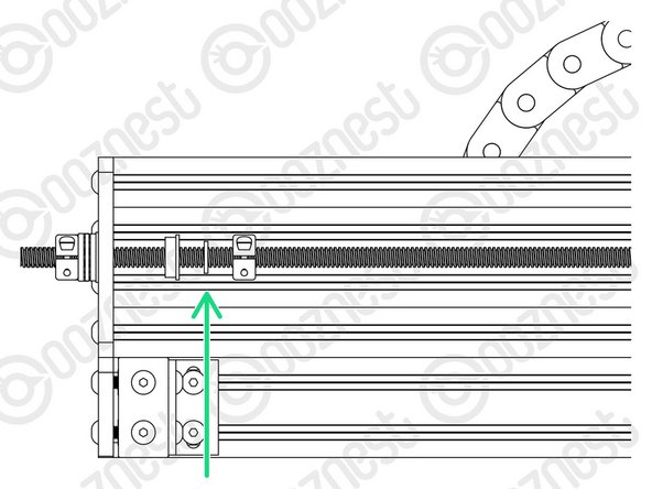
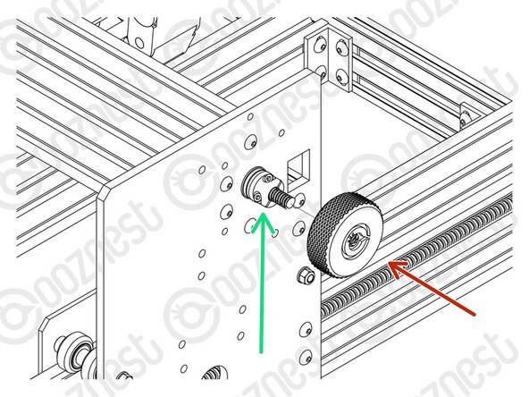
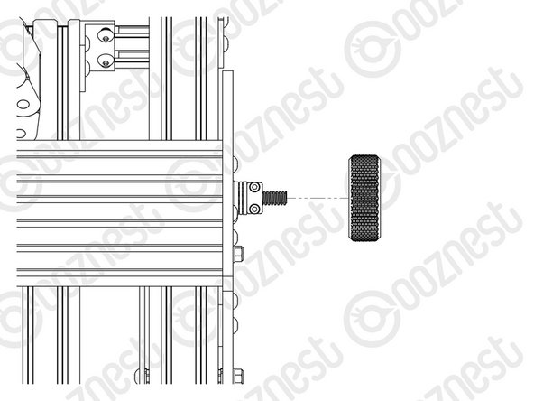
Starting with the X-Axis, thread on the Tensioning-Knob until it is up against the Clamping-Collar.
-
Then loosen the same Clamping-Collar.
-
Turn the Tensioning-Knob clockwise, you will feel the Lead-Screw tension build.
-
Keep turning until the Stepper-Motor clicks over.
-
Keep turning, just before the point that the Stepper-Motor clicks over again is the correct amount of tension for the Lead-Screw.
-
While at this point of tension, tighten the Clamping-Collar that is next to the Tensioning-Knob.
-
Remove the Tensioning-Knob.
-
Repeat all the above for both Lead-Screws on the Y-Axis.
I loosened the clamping collars according to the instructions, turned the tensioning knob clockwise, and know the drive screw has detached from the stepper motor entirely. There doesn't seem to be a way to reattach it. Nothing clicked, no tension built up, just turning the knob unscrewed the screw from the motor. What do I do?
Hi Aegir,
Please make sure the screw is reattached with the coupler gripping both the motor shaft and leadscrew securely, and tighten the coupler’s set screws so they lock both in place; otherwise the knob can unscrew it again. Can you check if you tighten the screws on the coupler to ensure both the motor shaft and the leadscrew are locked in place?
Let me know, and I’ll guide you further if needed!
Cyndy -
I did manage to get it to reattach, but I don't see how I can do this tensioning knob business without it coming off again.
Aegir -
Hi Team, I am quite confident that I did the tensioning correctly as described here, however when I home the machine and test how tighten the lead screws are I am not totally confident as they can be moved up and down quite easily. From the video linked in the previous comments is difficult to tell. Can you please provide a feedback or a video showing what is the right tension? Thanks!
Julien Moro - Resolved on Release Reply
Hi Kimberley, thanks for the support! I actually found a video that clears up any doubt and might be helpful in the future for other people:
https://www.youtube.com/watch?v=YoSoj-f9... at 2:00 shows exactly the difference. Seems normal that the lead screw still moves a little.
Hope it helps!
Hi Julien,
With the motors locked, rotate the tensioning knob, you will feel the tension build and then a thumpy click, this is the motor clicking over as it can only hold so much torque. Just before this clicks over is the correct tension that you need to tighten your clamping collars. Make sure your flexible couplers are securely tightened as per the guide.
Eire Workshop has a good video showing the tensioning here - https://www.youtube.com/watch?v=1MgonULT...
Thanks.
I'm having the same problem where the X stepper won't click. If I keep turning the tensioning knob it will eventually pull the lead screw out of the Flexible-Coupler. I tried powering off and on again and the stepper turns freely; sending command M17 locks it but it still won’t click over.
I realised that when the lead-screw was pulled out of the Flexible-Coupler all the bearings parts fell off. After reassembling all the parts the tensioning procedure now works successfully.
Simon -
If I leave the outer clamping collar tight, turning the tensioning knob rotates the lead screw which makes the stepper click. If I loosen the clamping collar, turning the tensioning knob pulls the lead screw out without rotating it, which is why the stepper does not click.
Simon -
Hi,
I tried tensioning but nothing happened and instead it kept rotating.
There was no click of any kind.
I imagine this is because it wasn’t moving the stepper motor?
Or maybe something to do with the thrust bearings?
Appreciate any help. Was all going so well until this point 😂
Chris
I’m really struggling here. What does click-over mean? Does it mean the stepper shaft rotates? How can it if it’s locked? I’ve managed to pull the lead screw out of the tensioner more than once now. No idea how tight those screws should be. I don’t want to over tighten and wreck the hexes. Will see if there’s a video out there on this.
Hi Spoon,
With the motors locked, when you rotate the tensioning knob, you will feel the tension build and then a thumpy click, this is the motor clicking over as it can only hold so much torque.
Just before this point is the correct tension.
There is a video here: https://www.youtube.com/watch?v=1MgonULT...
Thanks
Robert -
Can I just suggest that you edit the instructions so they read “Keep turning, just before the point that the Stepper-Motor clicks over AGAIN is the correct amount of tension for the Lead-Screw.” Not knowing exactly what noise the stepper motor should make when it clicks over, I thought I had just knocked something and carried on a couple more times. Hoping I got away with it.
cant edit my comment but the instructions DON’T tell you to center both the X and Y axis..
Neil Dilly - Resolved on Release Reply
ok i must be incrediably stupid…. followed the instructions to remove the clamping collars but had to switch off the machine to move the collars to a position i could loosen the grub screws.. switch machine back on and its showing theaxis not homed… so i turn the tensioner as instructed and have destroyed the X axis limit switch… can i just point out that the instructions do tell you to move the x axis into the center of the machine as well as the Y….. now have a useless lump of aluminium sat on my work bench..
Neil Dilly - Resolved on Release Reply
Hi Neil,
Thanks for your comment. Sorry for any confusion, the instructions did imply that:
“Home the machine and use the jog buttons to move the machine roughly into the middle of the working area.”
But I am going to change it to make it super clear:
“Home the machine and use the jog buttons to move the machine roughly into the middle of the working area in X & Y.”
Regarding your broken limit switch, just shoot us an email and we can replace it.
Robert
Robert -
Just following the instructions:
Keep turning until the Stepper-Motor clicks over.
Keep turning, just before the point that the Stepper-Motor clicks over is the correct amount of tension for the Lead-Screw.
So I have understood this correctly, turn until the stepper motor clicks over once, and then continue turning and stop just before it clicks over a second time?
Alec Thorne - Resolved on Release Reply
Hi Alec,
That is correct. The first click over is really just so you can get an idea of the amount of force required.
Robert -
Hi Ryan, when I 1st did this step, I turned off the controller for safety. After I had completed the tensioning I realised that the controller needed to be on to lock the stepper motors. Maybe you could mention that in the instructions.
Ian Martin - Resolved on Release Reply
-
-
-
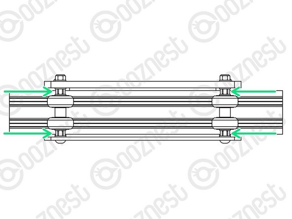
Once all 3 Lead-Screws are tensioned, put back the Flanged-Radial-Bearings, Rubber-Bushings, and Clamping-Collars that are on the inside channel of Extrusion-E/F on the X & Y Axes.
-
The Clamping-Collars only need to be pushed lightly up against the Rubber-Bushings & Flanged-Radial-Bearings. Tighten the Clamping-Collars.
-
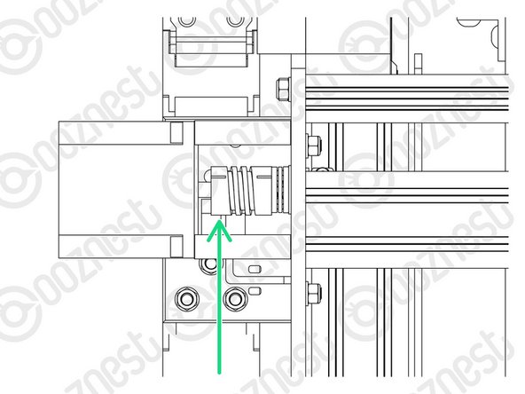
We need to release any tension inside the Flexible-Couplers.
-
On the Stepper-Motor side of the X & Y-Axis Flexible-Couplers completely loosen the grub screws and clamping bolts.
-
Then completely tighten the same grub screws and clamping bolts.
-
Make sure you do this to the Stepper-Motor side of the Flexible-Coupler.
-
If you loosen the Lead-Screw side you will loose all tension in the Lead-Screws and you will need to redo it.
-
Tighten all the Nut-Blocks on the X & Y-Carriages. While doing so, squeeze the Nut-Blocks together to remove any backlash.
After tensioning the lead screws I found it impossible (for the Y axis anyway) to reinsert the flanged bearings back into the holes as the lead screws were slightly off-centre. The only way I could make this work was by leaving the bearings in the holes while doing the tensioning.
When I loosen the screws the flexible coupler turns so the grub screw doesn't sit at the flat end any more. Does this matter? Do I switch off the machine to turn the stepper motor? Ta.
Rolf Black - Resolved on Release Reply
-
-
-
Home the machine.
-
Then turn the machine off.
-
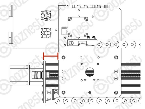
On the left Y-Axis (The side with the Limit-Switch) measure the distance between the back of the Y-Carriage and Y-End-Plate.
-
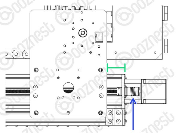
On right Y-Axis measure the same distance.
-
Rotate the Flexible-Coupler by hand until it matches the left Y-Axis.
-
-
-
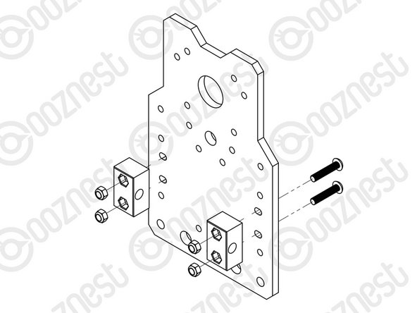
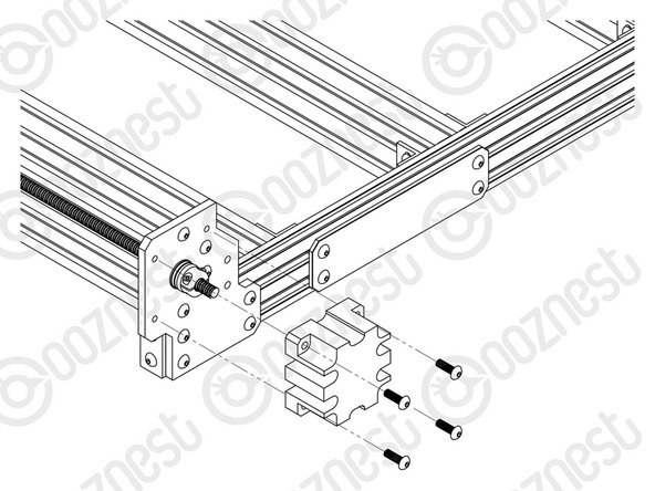
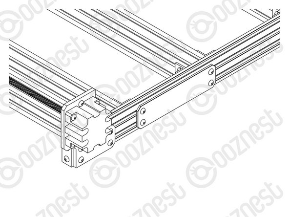
Using 12 x M5-Button-Head-Bolt-16mm attach 3 x Lead-Screw-Caps over the bare ends of the X & Y-Axis Lead-Screws.
The lead screws are sticking into the end caps slightly, causing a slight bulge. Is this a problem? The machine itself seems to jog fine despite this.
I could see a case for simply removing the screw caps, or for adding spacers to them to provide some distance.
Hi Lily,
Your lead screws should not be touching the inside of the endcaps. If they are, then you probably do not have the correct distance protruding on the opposite end.
Thanks
-
-
-
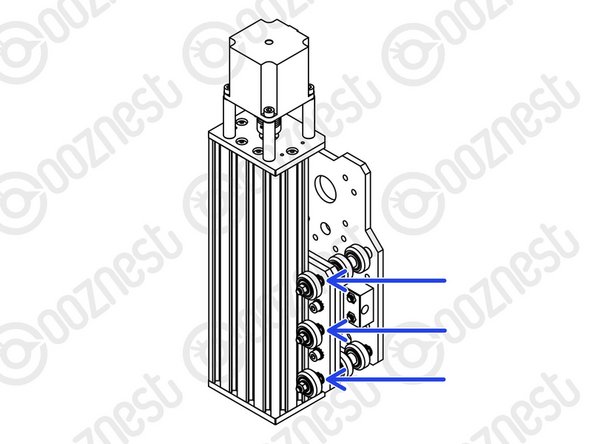
In the 'Extras' box there is an Eccentric-Spacer-Spanner.
-
This is shaped to give you access to all the Eccentric-Spacer-6mms without needing to move your machine.
-
Eccentric-Spacer-6mms should be adjusted until there is a small amount of friction between the Solid-Wheel & Extrusion.
-
Check there is also no play in the carriage if you try to wobble it. The Eccentric-Spacer-6mm will remove this if adjusted correctly.
-
Adjust the Eccentric-Spacers on the X-Carriage.
-
Adjust the Eccentric-Spacers on both Y-Carriages.
-
Adjust the Eccentric-Spacers on the Z-Axis.
-
We recommend periodically checking the Eccentric-Spacer-6mms throughout the use of the machine.
Does it matter if all 8 wheels on a carriage have exactly the same tension? Are we trying to achieve every wheel being the same, or just all have some friction, and none rock solid? Attempting to get all the same has so far taken two days and my thumbs will never be the same. Could the spacers be moved to the top instead of the bottom? Are there any design or function reasons why not? If so, I will buy a wheel set and move all mine to the top?
Hi George!
Each wheel should have some friction, but none should be rock solid—consistency is key for smooth movement. The eccentric spacers must stay on the bottom, as moving them would affect the adjustment mechanism. If you're struggling with adjustments, try making small incremental tweaks and checking the movement frequently rather than aiming for perfection all at once.
Let us know if you need further help!
Cyndy -
In the next design revision it would be helpful for adjustment if the x and y eccentric spacers were at the top rather than the bottom
Stephen White - Resolved on Release Reply
I have been very careful not to over tighten the wheels along the build process and yet I now have visible cracks in 6 on the machine. Some are under the y carriages so will be an absolute pain to replace. Suggest a slightly more definitive guidance on acceptable eccentric clamping force would be useful as part of the build instructions.
Roy Poulton - Resolved on Release Reply
Except for the Z axis, I’ve found that some of the wheels have no friction on the extrusion at all. Adjusting the eccentric spacer to give them some friction results in the opposite wheel (on the up or down side) being pretty much rock-solid (or at least barely movable by hand). Is that supposed to be like that?
Hi Bart,
If the wheels are rock solid, you need to adjust the eccentric spacers, so they are not clamped as tight.
We have a video here which instructs how to calibrate the wheels properly - https://www.youtube.com/watch?v=-FHBeNOo...
Have I built my workbee incorrectly? The Eccentric-Spacers on my Y carriages are at the bottom. After fixing my CNC to the bench, they are almost impossible to access.
Mark Williams - Resolved on Release Reply
Hi Mark,
Yes, that is correct. There is a small spanner with the machine, this should be used to adjust the eccentric spacers on the underside.
Robert -
Robert, that worked a treat. The spanner could do with being a little longer for more leverage though :-)
Am loving the build!! Thanks to everyone at Ooznest..
Alec Thorne - Resolved on Release Reply
Eccentric-Spacer-6mms should be adjusted until there is a small amount of friction between the Solid-Wheel & Extrusion.
I am not sure what a small amount of play should be. How can this be measured when the lead screws are stationary and the wheels cannot be turned? Does this mean that the wheels should be loosened to the point that they can slightly rotate when turned with the hand while the lead screw are still stationary?
Alec Thorne - Resolved on Release Reply
Hi Alec,
Thanks for your email, it is a small amount of friction. The wheel should still rotate on the Aluminium Extrusion, even though the Lead Screw is holding it in place on the gantry.
If the wheels are rock solid, you need to adjust the eccentric spacers, so they are not clamped as tight.
Robert
Robert -
-
-
-
It is nice to finally start moving the machine!
-
Guide Complete - Proceed to 3. Spoilerboard
-


Thanks for following the guide. Testing of the WorkBee is now complete!
Thanks for following the guide. Testing of the WorkBee is now complete!
Cancel: I did not complete this guide.
44 other people completed this guide.

2 Comments
Using 16 x M5-Button-Head-Bolt-16mm attach 3 x Lead-Screw-Caps over the bare ends of the X & Y-Axis Lead-Screws.
This had me hunting around trying to find 16x M5 16mm bolts for a good five minutes before I realised that three caps with four bolts each only needed twelve total. Somehow I only had six, so each one got two.
Jack O'Hara - Resolved on Release Reply