
-
-
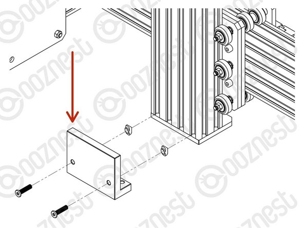
Attach the Z-Bracket to the Router-Clamp using 3 x M8-Cap-Head-Bolt-8mm. (Please note in your kit these may be M8-Cap-Head-Bolt-10mm)
-
-
-
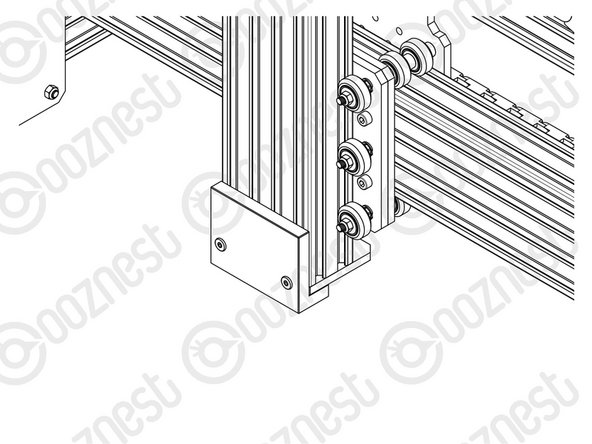
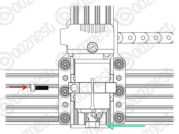
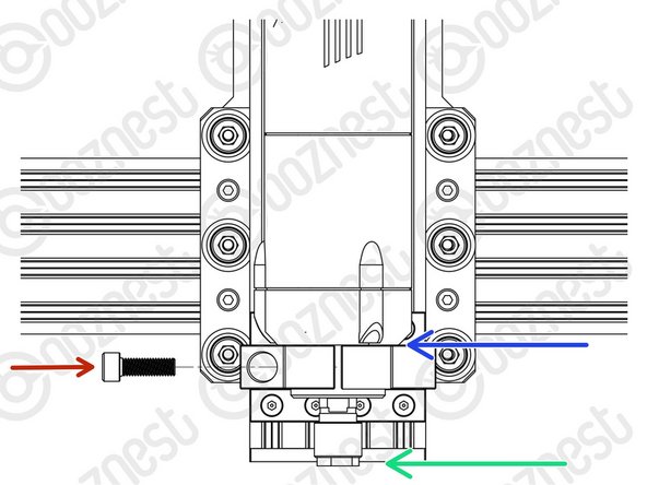
Insert 8 x M5-Button-Head-Bolt-12mm through the Z-Bracket.
-
Slightly thread a M5-Drop-In-Tee-Nut on to the end of each bolt.
An assembly tip: The instructions above saying to “Slightly thread a M5-Drop-In-Tee-Nut on to the end of each bolt.” needs to be followed! Only mate up the screws and drop-in-tee-nuts by 1 to 1-1/4 turns before installing your router mount. If you mate them up tighter to begin with, you will run the risk of not engaging the slots in the extrusion. This would probably result in your mounted router coming off the extrusion while working on a project because the drop in tee-nuts didn’t clamp down tight enough to secure the mount.
Tom Hawkins - Resolved on Release Reply
Using the m5 x12mm bolt and measuring the thread protruding through the back of the plate and the depth to the top of the nut you only get 2mm, ish of thread into the nut.
I have used M5 x 16 bolts with a spring washer under the head The thread passes through the nut and stays short of the extrusion slot.
fred TOMLINSON - Resolved on Release Reply
-
-
-
Reference the correct face of the Height-Reference-Tool for your Router Head.
-
50.00mm - WorkBee Router Head/Katsu/Makita/DeWalt Routers.
-
17.60mm - Mafell/Kress/Festool Spindles.
-
Attach the Height-Reference-Tool to the bottom of Extrusion-D using 2 x M5-Button-Head-Bolt-12mm and 2 x M5-Drop-In-Tee-Nuts.
-
The Height-Reference-Tool should be pushed up as high as possible.
-
Do not over-tighten the 2 x M5-Button-Head-Bolt-12mm.
-
The Height-Reference tool will be removed later.
When I attach the m5 button head bolts - 12mms, they are too large for the groove and the plate is pushed outwards before the tee nuts bite. I am not sure how to fix this, do you have any advice?
Hi Chris,
What do you mean by too large for the groove, do you mean the width of the bolt is larger than the width of the groove?
Robert -
same thing with my Z lead screw. can't use the reference plate. This step should also be done earlier to make it so so much easier during the X axis assembly. this could be done before fixing the bottom plate and then a set of t nuts could be used instead of drop in t nuts. So frustrating when the t nuts don't align and you can't see them when it is all upright.
Richard Jackson - Resolved on Release Reply
Hi Richard,
If the lead screw is protruding, it would need to be pushed up further.
Thanks.
I now realise how stupid I was…found out that the short side of the “L” is the 17.6 and the longside is the 50mm…a “Homer” moment there!!!
Ivan Flack - Resolved on Release Reply
Are there TWO different Reference Plates then?
From Above:
50.00mm - WorkBee Router Head/Katsu/Makita/DeWalt Routers.
17.60mm - Mafell/Kress/Festool Spindles.
I have a Mafell Router but the supplied plate says 50mm??? Is this correct or am I reading the steps incorrectly?
Do I just put on the 50mm Plate?
Regards
Ivan Flack
Ivan Flack - Resolved on Release Reply
Hi Ivan,
Glad you worked it out.
The height reference tool is just to get the correct height of the router mount.
The 17.6mm side is for the Mafell.
The 50mm side is for all others.
Thanks.
Robert -
I had the same issue as Tomasz with the lead screw protruding beyond the surface. A hole in the large face of the reference tool, so the protruding screw would not interfere with the reference tool, would be sufficient to make it work as described.
John Moffat - Resolved on Release Reply
Hi, just to make sure, the “2 x M5-Button-Bolt-12mm” is different from “M5-Button-Head-Bolt-12mm” ? Seems that my kit doesn’t have any bag labeled as M5-Button-Bolt-12mm. Thanks!
Jokke the Machinist - Resolved on Release Reply
Hi Jokke,
That was a typo in the guide. I have just fixed it to be M5-Button-Head-Bolt-12mm
Robert -
Hi Tomasz,
Thanks for your email. Ok yeah, your lead screw is slightly too long.
Could you email us here and we can send a replacement: https://ooznest.co.uk/help/
Robert
Hi Robert,
sorry for the delay, had other projects :)
The Z lead screw is 283mm in length, spacers are 40mm, C-beam extrusion length is 252mm. I also have a touch probe and I noticed that motor sits at a slight angle after mounting it. But that wouldn’t add more then 0.5mm in the sense of motor shaft down movement in Z direction. I may add spacers to compensate for that.
This step doesn’t work for Mafell router. My Z axis lead screw sticks out around 2 mm from the bottom of assembly even if it touches stepper motor shaft at the top end. The Reference Tool simply can’t by used as intended. I had to measure the distance and set the router mount assembly parallel to Y rail instead. I would suggest you either make Z axis lead screw shorter around 5 mm or add the hole in the reference tool on the etched side to allow space for sticking out Z axis lead screw…
Hi Tomasz,
Thanks for your email. That is strange, the first time I have heard this happen. Your lead screw should be 281mm, is it that length?
What length of your aluminium spacers on the stepper motor, they should be 40mm.
And is the C-Beam Extrusion 250mm?
Robert
Robert -
-
-
-
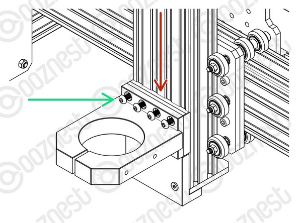
On one face of the Router-Clamp there are 4 threaded holes. These should be face down.
-
Sit the Router-Mount-Assembly on top of the Height-Reference-Tool.
-
Fix the Router-Mount-Assembly to Extrusion-D.
-
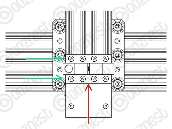
Tighten the 8 x M5-Button-Head-Bolt-12mm inserted previously.
-
Make sure M5-Drop-In-Tee-Nuts are engaged with the slots on Extrusion-D.
-
Remove the Height-Reference-Tool.
-
The Height-Reference-Tool is no longer needed.
-
But it can come in handy. It has an etched ruler to measure end mill stick out.
so i just found out that if you unscrew the bolts with the drop in t-nuts all the way, and then tighten again, they'll naturally flip and engage perfectly and almost 100% of the time. so if you just place the assembly and then press it against the x-axis while unscrewing one of the bolts and then retightening, then you can let it go and do the rest.
Thanks for this.....
I have decided I hate tee-nuts but for the drop in type this definitely worked for me too.
The way I did it, height reference tool went on last.
Put in 4x M5-Drop-In-Tee-Nuts into Extrusion D and rotate to engagement position. Repeat again with another 4 so you have 8 x M5-Drop-In-Tee-Nuts in position.
Offer up router mount and attach the top 4 Button Head Bolts. Slightly loosen and slide up until bottom 4 holes are aligned with the bottom Drop In Tee Nuts and insert the other 4 ButtonHead Bolts .
Slide router mount up half way and tighten 1 bolt to hold in position.
Now instal height reference tool. Once secure slide router mount down on to it slowly so Drop In Tee Nuts do not turn.
Tighten Bolts on router mount and then remove height reference tool.
Was a bit fiddly but found it much easier to make sure Drop In Tee Nuts were correctly engaged.
Okay, that’s how I did it: I did this step after assembling the X-Gantry so I could lay it on its side. I didn’t attach the Height-Reference-Tool for the Router Head but inserted the first 4 M5-Drop-In-Tee-Nuts. Then I screwed in the first 4 M5 while alligned at the bottom and tightened so I could still just slide up the router mount. After sliding upi the mount carefully I inserted and aligned the next 4 nuts and slid down the mount to be able to screw in the next 4 M5, tighten until mount still movable. Push up carefully with hight reference tool to crrect hight, making sure the nuts don’t turn and tighten all screws at correct hight. There is probably a much easier way but this worked for me…
Rolf Black - Resolved on Release Reply
Any handy hints to make sure the M5-Drop-In-Tee-Nuts stay engaged with the slots on Extrusion-D? Mine keep turning, difficult enough to turn them to engage in the first place… Thanks
Rolf Black - Resolved on Release Reply
-
-
-
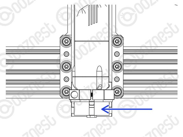
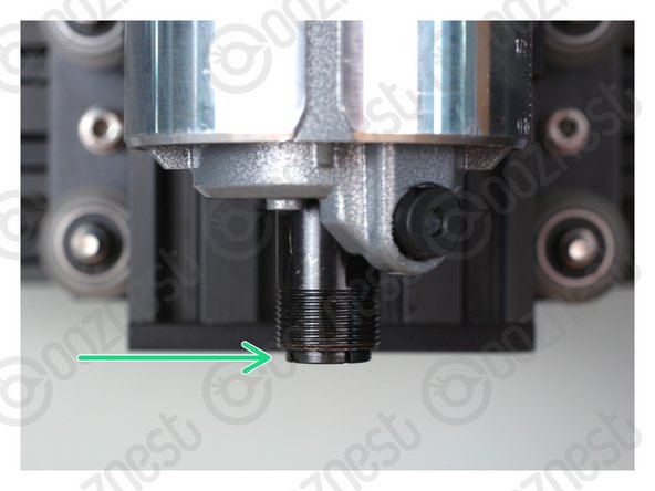
Insert the Router Head into the Router-Clamp and tighten the clamp using the M8-Cap-Head-Bolt-25mm.
-
For WorkBee Router Head/Katsu/Makita/Dewalt Routers position it with the collet flush with the bottom of the Z-Axis.
-
For Mafell/Kress/Festool Spindles position the body flat on the top of the Router-Clamp.
-
Do not overtighten the Router-Clamp.
-
It should be tightened no more than the point that the Router Head can no longer be rotated by hand.
-
Any tighter and you will run the risk of pre-maturely wearing the brushes of the Router Head.
-
The power wire of the Router Head should run vertically up to the ceiling. If you have a Dust Shoe, it can be clipped to the extractor hose.
-
Do not put the power wire inside the drag chains of the machine. It is a high power wire and should not run alongside the other wires.
Hi Emily,
I'm sorry to hear you're seeing dents and scratches with your router head. Can you please reach out to our support team and provide more details? https://ooznest.co.uk/help/
We're happy to resolve this for you.
Cyndy -
When installing the router flush I have noticed my lead screw is sticking out of the bottom by 4mm and not flush is this an issue? Or do I need to reseat the lead screw higher up?
gibsrich@hotmail.co.uk - Resolved on Release Reply
Hi, Yes the lead screw needs mounting further up. The Lead Screw should be touching the stepper motor shaft.
Robert -
unfortunately i wasnt able to attach the Mafell router either with the 2mm bolt.
i did as recommended above to get extra leverage, and the only thing that happened was that the bolt now is stripped out and i cant get it out of the router clamp.so what are my options now? Drill it out and get a new longer bolt?
Hi Elias,
Sorry about your issues. Please contact us here with your Order ID and we can sort out a replacement: https://ooznest.co.uk/help/
Robert -
I also have the Mafell spindle, 43mm mount and had the same problem, I figured equipment engineered and designed so well cannot have a simple ‘bolt too long’ problem. I removed the 25mm bolt and noticed grey dust around the thread which I assume is residue from tapping. So I removed the mount and extracted a cloud of dust with a cotton bud.
I decided to tighten the bolt with the spindle flat on the workbench, blob of grease on the bolt and used a length of copper pipe as leverage on the Allen key, It took several 1/4 turns and the spindle was still way too loose. I was sure the mount would crack before it completed and the sound from the bolt was horrendous, but suddenly a final turn and the spindle went from loose to rock solid. So a couple of turns back, removed spindle and re-installed the mount. Only took a couple of 1/4 turns and the spindle was locked again.
So fear not and persevere. The bolt is not too long, will not bottom out and does not require washers!
Brilliant piece of engineering!
Craig Sutherland - Resolved on Release Reply
I had the same problem that the bolt was too long. I used two spring washers, in effect to shorten the bolt from 25mm.
John Moffat - Resolved on Release Reply
Really had some problems with too. Final solution seemed to be brute force and ignorance. I think its something I’ll definitely have to keep an eye on to make sure the Mafell stays secure.
Maybe a shorter bolt guys?
Hi Craig,
25mm is the correct length for the design, the mount is a big chunk of aluminium to compress round the router head, so sometimes the bolt head just requires a pinch using an hex driver and wrench.
Robert -
I have the Mafell router and am finding I have the same issue as the other guys above. The M8 x 25mm bolt seems to be bottoming out before any clamping has been achieved. I ran an M8 tap just in case it was the thread, but that bottoms out too. I may be wrong but to me it seems like the counter bore for the head of the bolt is too deep. Solutions could be a shorter bolt or a new Mafell 43mm clamp with the correct bore and thread depths. I’ll see if I can source a M8 x 20mm bolt locally tomorrow to see if that fixes things.
Colin Turner - Resolved on Release Reply
Thanks for the offer, Robert. However, I already have it fixed. I got a longer bolt from a local hardware store. I would like to add that I retaped the hole (M8x1.25) and got the original bolt to connect with the threads. However, I was only able to get approximately 1 to 1-1/2 turns on the bolt. When I tried to apply any pressure, the single thread stripped out. Perhaps the counterbore was too shallow. I didn’t have a counterbore bit to machine it deeper.
Tom Hawkins - Resolved on Release Reply
I got the DeWalt router mount. The M8 x 25mm Cap Screw is too short to engage the threads. Had to go and purchase a M8 x 30mm SHCS.
Tom Hawkins - Resolved on Release Reply
Hi Tom,
Strange 25mm should be long enough, the start of your thread must be missing. We can replace if needed?
Robert -
Hi, I have the same problem as the above two comments - cannot get the clamp to tighten on the mafell router. Could I get a replacement?
Huxtable Joinery - Resolved on Release Reply
Hi,
Have you got something to get a bit more leverage on the bolt, it probably only needs an extra 1/4 turn to clamp the Mafell. Using a screwdriver with a pair of adjustable pliers on the handle works well.
If not email us for a replacement: sales@ooznest.co.uk
Robert -
There was no way I could get the clamp to work with the Mafell. The thread sounded awful even after blowing out with a compressor, tried grease and I hit the bottom of the thread. I’ve had to add a spring washer to the bolt to get enough clamping force and even then it was only just enough.
Tim Wiseman - Resolved on Release Reply
Once I have finished the machine I’ll do some checks to see if it is secure and let you know.
Hi Tim,
Thanks for your email.
Sorry about this, it should not be like this, it must be a faulty thread. Would you like a replacement sent?
Robert -
At first I could not get the clamp to tighten on to the mafell and im used to agricultural machinery. A touch of grease on the seating of the bolt eased the friction and I got the extra half a turn.
Frank Triggs - Resolved on Release Reply
Frank Triggs, Thankyou for your comment, did exactly as you said and it worked a treat!
-
-
-
When using the Dust Shoe, please make sure there is adequate strain relief on your extractor hose. If there is no strain relief, it will break the extractor port on the Dust Shoe.
-
Dust-Shoe-Adaptors will be included in the 65mm (WorkBee Router Head/Katsu/Makita) and 43mm (Mafell/Kress/Festool) versions of the Router Mount.
-
WorkBee Router Head/Katsu
-
The 65mm Dust-Shoe-Adaptor sits inside the Dust Shoe. The Dust Shoe is then clamped around the body of the Katsu/Makita Router.
-
Mafell
-
This should only be installed if you have a Dust Shoe.
-
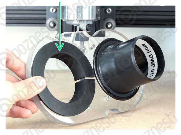
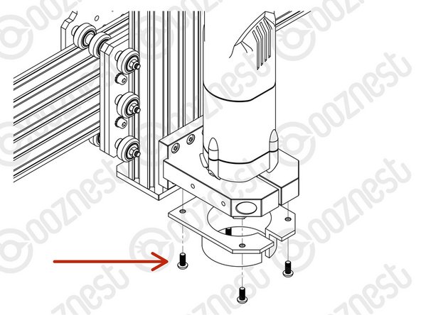
Attach the 43mm Dust-Shoe-Adaptor to the underside of the Router-Clamp using 4 x M5-Button-Head-5mm Bolts.
-
The Dust Shoe clamps around the circular portion of the 43mm Dust-Shoe-Adaptor.
Reference fitting the 43mm Mafell dust shoe adaptor. The holes have not been tapped on the underside of the router mount, or they have been tapped incorrectly. I have tried the M5 Button Head 5mm Bolts and a load of other M5 (even M4) bolts. Nothing will catch a thread. Annoying given I am now fitting this upside down - I suggest this would be much easier to mount BEFORE the router mount assembly is fitted. And as I said threads that will accept a screw!
David Gracey - Resolved on Release Reply
Hi David,
Sorry to hear there is an issue with your router clamp, please contact us so we can look into this for you - https://ooznest.co.uk/help/
Thanks.
-
-
-
The Mafell FM 1000 is broken in by the Manufacturer so is ready for use.
-
For the WorkBee Router Head/Katsu, we recommend running it at a medium RPM, with no load, for 30-60 minutes.
-
Remove the collet and nut while doing this so it does not come off.
-
-
-
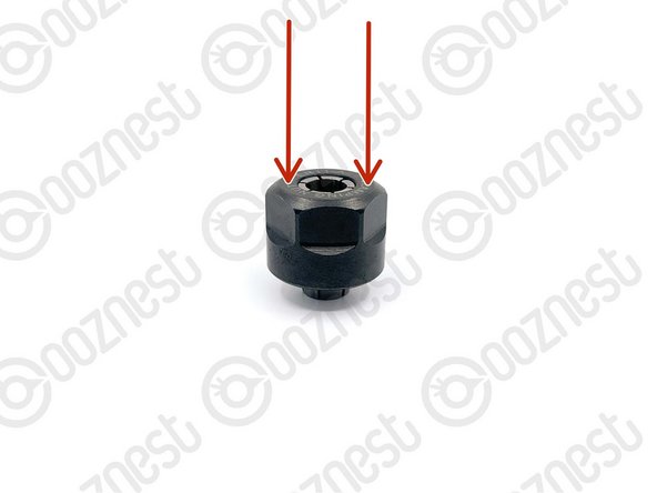
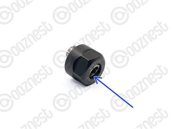
The collet must always be inserted into the nut before attaching it to the WorkBee Router Head or inserting an endmill.
-
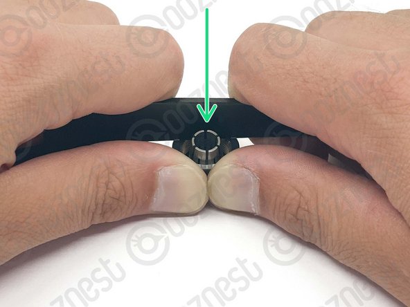
Place the collet into the nut and then turn it upside down onto a hard surface.
-
Apply downward pressure to the rim of the nut until it clicks into the retaining ring on the nut.
-
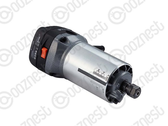
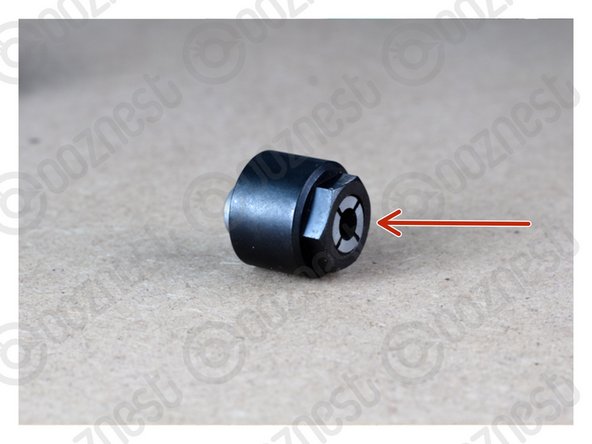
To remove the collet apply a horizontal force to the collet until it clicks out of the retaining ring on the nut.
-
Use the wrench provided with the WorkBee Router Head to get more leverage as demonstrated in Image 2.
-
Push the collet out of the nut on the side which has been released from the retaining ring.
-
Each collet can clamp -0.5mm below its rated size. For example, the 1/4" collet (6.35mm) can clamp down to 5.85mm.
-
-
-
Always use the correct collet size for the cutter.
-
Mafell
-
Click the collet into the nut first, then insert the end mill fully.
-
Fix the collet with a maximum torque of 10-11Nm. Tighten the collet by hand, then a 1/8 turn with a spanner, this should be about right.
-
Keep the collet lubricated with a solid lubricant (e.g. Molykote P-40) or by lightly greasing.
-
Katsu
-
Push the collet into the shaft and then the nut over it. The end mill can then be inserted fully.
-
Only use the button on the side to hand tighten the collet. To fully tighten, use two spanners, a 13 spanner on the flat portion of the shaft, the included 22mm spanner on the collet nut.
This could do with a bit more explanation. I think my Mafell collet has been already assembled, it already looks like the picture with the red arrow. But… is that whole thing the end mill? Where do I put the lubricant?
Hi Aegir,
The endmill is not in that picture. The endmill goes into the collet.
The grease should go on the outside of the collet.
Thanks
Robert -
-
-
-
Starting to look like a CNC Machine now. Now we begin the electrics.
-
Guide Complete - Proceed to 1. Drag Chains
-


Thanks for following the guide. Any issues, please contact us!
Thanks for following the guide. Any issues, please contact us!
Cancel: I did not complete this guide.
62 other people completed this guide.

3 Comments
Total newbie here... I understood step 8 like you had to press the collet through, and free of the nut. But the nut and collet was already correctly inserted into each other when delivered (for the mafell). I managed to apply a lot of pressure with extra tools before realising what was wrong. Thanks for a great guide though.
Best regards Søren
Søren Storm - Resolved on Release Reply
Apologies, I had a small issue with the reference gauge and then forgot to follow it up. Life complexity got in the way. The bottom plate is fixed to extrusion D by protruding bolts. For the Mafele router this does not allow the height reference tool to sit against the bottom plate or give the cam nuts the space to locate in the face of extrusion D . I have taken pics of the situation but i am not sure now where to send them. The router was easily fixed in place level, and at correct height, using a custom made L section bit of hardwood. Couple of mins on the table saw. The workbee is now finished and running ( I love it and really enjoyed the build) but I need a bit of chat about the code my post outputs and its interaction with the workbee controller.
Frank Triggs - Resolved on Release Reply
Hi Frank,
Thanks for the pictures you emailed to us. I think it is because the z-plate is round the wrong way. The z-plate on one side has counter-bores for the heads of the bolts to sit in.
Robert
Robert -
Hi Emily,
We're sorry to hear this. Please reach out to our support team at https://ooznest.co.uk/help/ so we can resolve this for you.
I look forward to hearing from you soon!
Cyndy - Open Reply
My Z Bracket has been put in a bag labelled wrongly “Height Reference Tool” (as I already have the actual Height Reference Tool in the box)
emily - Open Reply