
-
-
Assemble the top right Solid-Wheel set first. Insert a M5-Button-Head-Bolt-30mm through the Z-Plate from the back.
-
The back is the side with the counterbores.
-
On to the bolt add an Eccentric-Spacer-6mm. (Rounded portion into the Z-Plate)
-
Then add a Precision-Shim - ->- - Solid-Wheel - ->- - Precision-Shim
-
Finally add a M5-Nyloc-Nut. This can be tightened. Ensure that the Solid-Wheel still rotates freely.
-
Repeat the above for the other 2 x Solid-Wheel set on the right row.
-
Repeat for the 3 x Solid-Wheel sets on the left row, but use a Aluminium-Spacer-6mm instead of each Eccentric-Spacer-6mm.
-
-
-
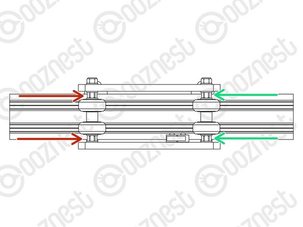
On the hexagonal portion of the Eccentric-Spacer-6mm, there will be a face that is marked with ‘6mm’.
-
Using a 8mm spanner, rotate each Eccentric-Spacer-6mm so that this face is facing right. (Doing this maximises the gap between the left and right row of Solid-Wheels)
-
Insert Extrusion-D in-between the two rows of wheels. Turn the assembly on to it's left side so Extrusion-D is sitting on the left row of Solid-Wheels.
-
Starting with the top right Solid-Wheel. Rotate the Eccentric-Spacer-6mm until there is a small amount of friction between the Solid-Wheel and Extrusion-D
-
Repeat for the bottom right Solid-Wheel. Then repeat for the middle right Solid-Wheel.
-
Slide Extrusion-D back and forth. This should require a small amount of force, and all Solid-Wheels should spin.
-
Check there is no wobbling of Extrusion-D. Once happy, double-check the tightness of the M5-Nyloc Nuts and remove Extrusion-D.
-
Try to get all the Solid-Wheels touching Extrusion-D as best as possible. If not, it is not a problem, we will check the Eccentric-Spacers-6mms again once the machine is built.
When adjusting the eccentric spacers I found you may get one wheel nicely tensioned and then when you adjust the next it has made the first wheel slightly loose, able to spin without moving the extrusion, going back and forth to tweak all of them until they all move the extension on the eccentric spacer side and the normal spacer side.
Same problem as the previous comments. A defect Nyloc nut caused the hex to wear out on the bolt head. Saw the comment that an extra four 30mm M5 button head bolts are provided - thanks. Are additional M5 Nyloc nuts also included?
Alec Thorne - Resolved on Release Reply
I have had the same issue of the hex warning out on bolts, I found this to be the Nyloc Nuts, I used my own M5 bolt with a better head for holding onto with a little wax and I pre-threaded each of the Nyloc nuts to ensure they would not get jammed tight when building the Z1+.
When performing this step one of my M5-button-head-bolt 30 mm head wore out. Made me crazy if you Britons had sent me a 1/8 or 9/64 (imperial) heads, or maybe 3.5. Now I think the M5 head was a worn 3.0. Is this correct…?
Hi Emil,
Thanks for your comment. Sorry about that, for the 30mm bolt, we provide 4 spare, so you can use one of these in its place.
Robert
Robert -
-
-
-
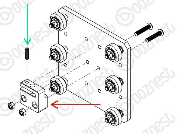
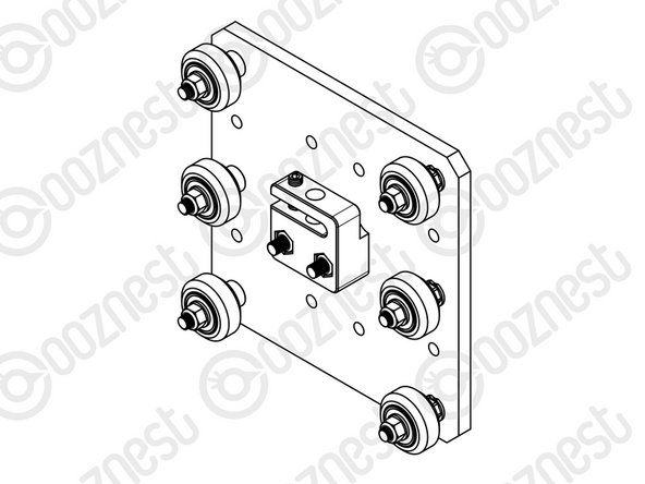
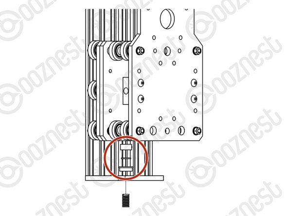
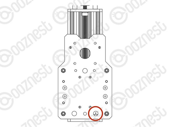
Attach the Z-Axis-Nut-Block to the Z-Plate using 2 x M5-Button-Head-Bolt-25mm & 2 x M5-Nyloc-Nuts.
-
In the Z-Axis-Nut-Block bag there is a set screw. Screw it into the top of the Z-Axis-Nut-Block until it just touches the surface on the opposite side of the gap.
-
The set screw will later be used to remove any backlash from the Z-Axis.
-
Discard the nut left in the bag with the Z-Axis-Nut-Block.
-
Moving forward this will be known as the Z-Plate-Assembly
-
-
-
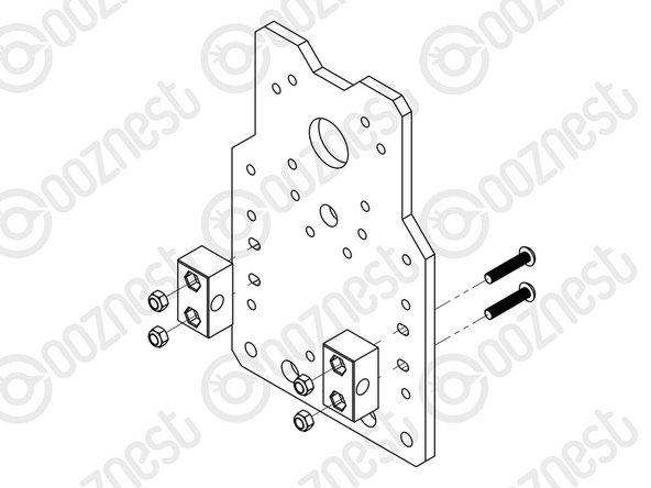
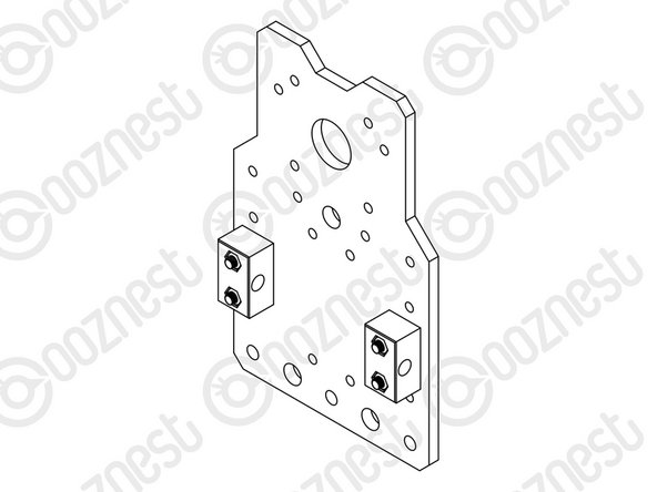
Attach 2 x Nut-Blocks to the X-Plate-Back using 2 x M5-Button-Head-Bolt-25mm & 2 x M5-Nyloc-Nuts.
-
Keep these bolts loose so the Nut-Blocks can still move side to side.
Hi Emil,
Thanks for your comment. Can you send an email with pictures to us: https://ooznest.co.uk/help/
Once we have that, we can resolve this for you.
Robert
Do not think the pictures will do too much, looks like a normal screwhead but the grip of my hex key is not good enough. I will try to put a think latex glove in between and see if I can get some traction. Not so much more to do unfortunately. Worst case I will drill and remove the screw and hope I have some spare in right dimension.
Emil -
One of four M5-Button-Head-Bolt-25mm head broke, now I can barely get it tighter and definitely not remove it….
Hi Emil,
Ok if you contact us here: https://ooznest.co.uk/help/
We can replace it and the bolts.
Thanks
Robert -
-
-
-
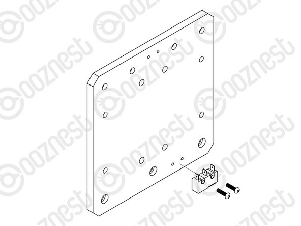
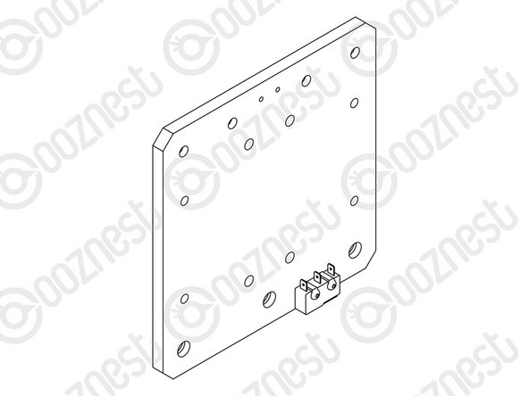
The Limit-Switches are located in the 'Wires' box. They have red/black wires attached to them. The wires are not shown in the assembly picture.
-
Attach the Limit-Switch-2 to the threaded holes on the back of the X-Plate-Front using 2 x M2.5-Button-Head-Bolt-10mm.
-
The back is the side without the counterbores.
-
Look at the Cheat Sheet to find the correct Limit-Switch.
-
The wire will be sorted later in the manual.
Limit switches are identified with a number around the wires near the white plug.
You drawing of the X-Plate-Front causes a bit of uncertainty. It looks like the holes adjacent to the limit switch location are counterbored on the back side.
Jacob Weiand - Resolved on Release Reply
This could really do with being clearer. Perhaps a photo rather than the diagram because like it was mentioned by Sam L, the diagram looks nothing like the wiring itself. Perhaps the wiring has now been changed as mine appears to come up from the switch and then has been moulded to bend at 90 degrees away from the X-plate. This means my red wire is on the left and black on the right. The opposite to what some suggest. Here’s hoping it doesn’t come back to bite me.
Hi Craig,
Thanks for your comment. Yes, the wires are now moulded at 90degrees. Attach the switch to the plate so the wires are coming away from plate. It does not matter which way round the colour of the wires are. Rob
Robert -
The limit switch wires run up the length of the X-Plate-Front. When inserting the Extrusion-D, this potentially rubs on the wires. Would you suggest maybe glueing a small rubber wire sheath onto the face of the plate to feed the wires through to reduce any possible wear?
Alec Thorne - Resolved on Release Reply
Robert, thanks for the quick reply. I will endeavor to read a few steps further before posting in the future… Am loving the machine build !!
Hi Alec,
The wires don’t run up the face of the X-Plate-Front, they feed directly opposite, into the hole on the X-Plate Back. You may just have to bend the wires slightly in that direction.
Robert -
Should the Red Lead be to the RIGHT or LEFT when the limit switch is mounted?
Ivan Flack - Resolved on Release Reply
Thanks Robert.
That was my assumption as well, that the switch was towards the bottom surface, i.e. not making it important which direction.
Emil -
Hi Ivan,
In the picture above the metal lever is pointing to the right. To be honest the orientation of the switch is not important.
Robert
Robert -
The limit switches look nothing like the diagram.
You'll find them tucked away in the wires box, with a spool of red and black cables already wired in.
You'll find the different numbers on a plastic tag attached to the cable.
Make sure the ‘switch’ is facing down and at the edge of the plate!
Hi Emil,
The metal portion of the switch should be as the image. This will orient it correctly.
Thanks
Robert -
Does it matter if the switch plate is pointing to the left or to the right? Which side of the switch should be towards the plate?
Emil -
Thanks Steve! Need to update that guys, just spent half an hour scouring through every box before coming to the same conclusion as Steve. Very confusing.
Sam L -
Hi Steve, thanks for your comment. Yes, the switches are in the Wires box. The wires are not shown in the image above. Once attached just leave the wire hanging for now. The metal part of the switch should be facing down.
Robert -
-
-
-
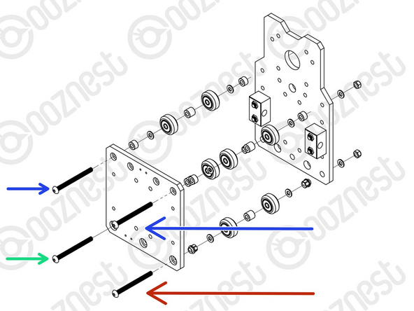
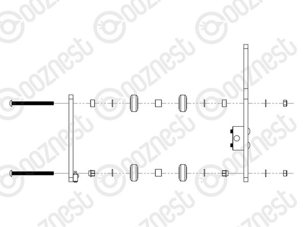
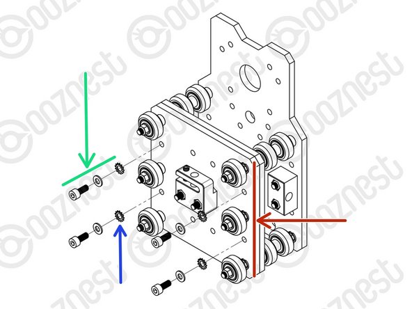
Assemble the bottom right Solid-Wheel set first. Insert a M5-Button-Head-Bolt-60mm through the X-Plate-Front from the front.
-
On to the bolt add an Eccentric-Spacer-6mm. (Rounded portion into the X-Plate-Front)
-
Then add a Precision-Shim - ->- - Solid-Wheel - ->- - Aluminium-Spacer-9mm - ->- - Solid-Wheel - ->- - Precision-Shim
-
Add an Eccentric-Spacer-6mm then the X-Plate-Back. (Rounded portion of the Eccentric-Spacer-6mm goes into the X-Plate-Back)
-
On the outside of the X-Plate-Back add onto the bolt a Precision Shim then a M5-Nyloc-Nut. Only slightly thread on the M5-Nyloc-Nut.
-
Repeat the above for the other Solid-Wheel set on the bottom row.
-
Repeat for the 2 x Solid-Wheel sets on the top row, but use a Aluminium-Spacer-6mm instead of each Eccentric-Spacer-6mm.
-
The M5-Nyloc-Nuts can now be tightened. Ensure that each Solid-Wheel still rotates freely.
Hi i only seem to have 10 Eccentric-Spacer-6mm. how do i go about getting them quickly.
Thank You.
nocatmcm@hotmail.com - Resolved on Release Reply
Hi there,
Please contact us at help@ooznest.co.uk or via our contact page here: https://ooznest.co.uk/help/, and we’ll assist you in getting the missing items as quickly as possible.
Cyndy
Cyndy -
I think this is a repeat of Emil’s comment.. The Solid Wheel sets on the top rows start with the 6mm aluminium spacer then precision shim then wheel then 9mm aluminium spacer then wheel but then you have a 6mm aluminium spacer before the precision shim in the illustration . Should the precision shim be before the 6mm aluminium spacer just before the bolt goes through the X-Plate-Back or should it be as the illustration shows which would be , spacer, shim, back plate ?
Hi David,
Thank you for pointing this out, the image is incorrect and will be fixed. The text is correct.
Thanks.
OK, I've fixed it now.
In case it helps anyone, in my case I was confused by the phrase: “The back is the side.” without the counterbores.” In reality the rear part, the one that is not seen in the drawing, is the one that IF YOU HAVE the countersunk ones.
All the best
jmsg62@gmail.com - Resolved on Release Reply
Hi Roberto, following up on David’s previous comment…
On my plate, if I place the switch on the side with the countersinks (because otherwise the 6 mm eccentrics could not be mounted) the two small holes for mounting the switch are on the left and not on the right as seen in the mounting figure.
Is this so or my plate is bad.
On the other hand, if I place my plate like the one in the switch mounting figure, the countersinks are ON the invisible part, the opposite of the switch mounting part.
All the best
jmsg62@gmail.com - Resolved on Release Reply
I noticed that in picture 1, on the X plate front, the 2 screw holes that are used to mount the limit switch are to the left of center (as views from the front, i.e wih counter bores). On mine they are to the right. This caused me to doubt if I had got something wrong.
Sorry Robert. I made a mistake. I’d delete my comment to avoid confusing others but it wouldn’t let me.
David -
Hi David, when viewed from the side with the counterbores, they should be on the left. If they are on the right, that would be an issue, and we can replace your plate. Please email us to sort this: sales@ooznest.co.uk
Robert -
Finding the placement of the precision shim on the upper screws a bit inconsistent. On one side plate-shim-aluspace and on the other shim-aluspace-plate. Should precision shim be towards wheel or plate because you are mixing it in each end of this step.
Hi Emil,
Thanks for your comment. The precision shims should be between the 6mm spacer and wheel, as per the image. The text is correct, it is working from the X-Plate-Front towards to the X-Plate-Back.
Robert -
-
-
-
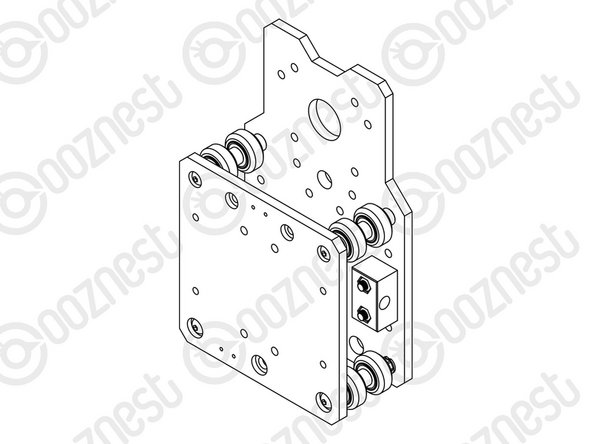
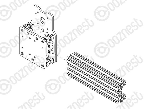
On the hexagonal portion of the Eccentric-Spacer-6mm, there will be a face that is marked with ‘6mm’.
-
Using a 8mm spanner, rotate each Eccentric-Spacer-6mm so that this face is facing downwards. (Doing this maximises the gap between the top and bottom row of Solid-Wheels)
-
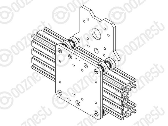
Insert Extrusion-D in-between the two rows of wheels. Turn the assembly upside down so Extrusion-D is sitting on the top row of Solid-Wheels.
-
Rotate both Eccentric-Spacer-6mms on one set of Solid-Wheels until there is a small amount of friction between the Solid-Wheels and Extrusion-D
-
Repeat for the other set of Solid-Wheels.
-
Slide Extrusion-D back and forth. This should require a small amount of force, and all Solid-Wheels should spin.
-
Check there is no wobbling of Extrusion-D. Once happy, double-check the tightness of the M5-Nyloc Nuts and remove Extrusion-D.
-
Try to get all the Solid-Wheels touching Extrusion-D as best as possible. If not, it is not a problem, we will check the Eccentric-Spacers-6mms again once the machine is built.
Hi it seems like i m short 4 Eccentric-Spacer-6mm. What should i do.
nocatmcm@hotmail.com - Resolved on Release Reply
Hi there,
We're happy to help you with the missing pieces for the Eccentric-Spacer-6mm. Please send us an email at help@ooznest.co.uk or reach out to us via our contact page for assistance: https://ooznest.co.uk/help/
Cyndy -
Hi @robertooznest, yes, but spotted now that you have to bend it 90’ deg. That works now, thanks.
Rolf Black - Resolved on Release Reply
Where should the cable be positioned? It is very close to the Extrusion D.
Rolf Black - Resolved on Release Reply
-
-
-
Mate the Z-Plate-Assembly to the X-Plate-Front.
-
The Z-Plate-Assembly should be orientated with the Eccentric-Spacer-6mms on the right side.
-
Secure using 4 x M5-Cap-Head-Bolt-12mm, 4 x Precision Shim and 4 x Locking-Washer.
-
The Locking-Washer should go in-between the Precision-Shim and Z-Plate.
-
Make sure the Z-Plate-Assembly is square to the X-Carriage-Assembly.
-
Do not over-tighten the M5-Cap-Head-Bolt. If over-tightened it will reduce the effectiveness of the Locking-Washer.
Hi Andy! We recommend to "tighten fully, then loosen by a single full turn" which is designed to allow for necessary adjustments in later steps. If you've already tightened these bolts fully without the subsequent loosening, you can simply loosen them by one full turn now. This adjustment will ensure that the assembly functions as intended in the following steps.
What happens if I’ve done this too right? I read this after I tightened it.
Andy Lander - Open Reply
A torque value would be great here rather than do not over tighten.
Jacob Weiand - Resolved on Release Reply
-
-
-
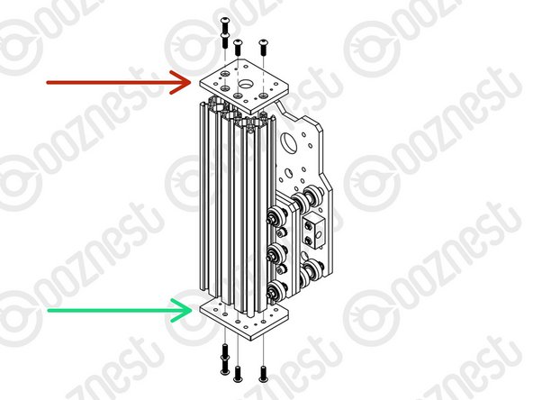
Slide Extrusion-D through the Solid-Wheels on the Z-Plate-Assembly.
-
Attach a Z-End-Plate to the top of Extrusion-D using 4 x M5-Button-Head-Bolt-16mm.
-
Tighten the bolts fully.
-
Attach a Z-End-Plate to the bottom of Extrusion-D using 4 x M5-Button-Head-Bolt-16mm.
-
Tighten the bolts fully, and then loosen by a single full turn.
-
The reason for this will become clear later.
Fixing the router mount at this stage before fixing the bottom plate would be so much easier and using t nuts instead of drop in t nuts. Doing this later is so fiddly and annoying. caused me about 1 hour delay due to the drop in t nuts not aligning properly and not being able to see if they were engaging when the whole thing is upright.
Richard Jackson - Resolved on Release Reply
Hi Richard,
Thank for your comment. With the router mount later in the guide, we advise threading the drop tee nuts just slightly on the bolts and aligning with the direction of the v-slot to easily slot in.
Thanks
Can you tell me why my Extrusion-D bottom end only have three threaded holes and not 4 in the Extrusion-D so i cannot fit the bottom plate as it looks like this has not been tapped out, very annoying as i have a day off work to build rest of machine and now i cannot continue. am i missing something or am i right
sales@badgerandbowl.com - Resolved on Release Reply
I’m finding that 3 of the bolts at the top are not winding all of the way in, as if they are too long for the hole.. by up-ending the extrusion-D and tapping it some swarf is falling out of the holes but this hasn’t fixed the issue. As such, having tightened them up, they are proud of the face of the Z end plate, and not holding the plate in place. Any suggestions?
Hi Matt,
Glad you got it sorted. If you would like a replacement piece of extrusion so you can use the correct bolts let us know.
Ideally they should be 16mm, so there is sufficient bolt engaging with the extrusion.
Robert -
Hey thanks for the reply, yeah I checked I was using the right bolts! In the end I dashed out to screwfix and grabbed some 12mm bolts so i could keep going. They seem to be doing the trick, do you think they will suffice? If not, what exactly would you like a picture of?
Matt -
Hi Matt,
Thanks for your message. Have you checked the bolt length is definitely 16mm?
If so, can you send some pictures to sales@ooznest.co.uk and we can sort a replacement piece of extrusion.
Thanks,
Robert -
I tightened as instructed now one of the screws at the bottom has rounded off so I cannot slacked by 1 turn. i hope this does not come back to bite me
Hi Richard,
There are spare of that bolt in that kit, so if you can get it undone, just replace it.
Thanks.
Robert -
Worth notifying that if U have a probe U have to tighten up those 2 screws that sit close to each other on the top , otherwise the probe “thing" will cover them and U will be redoing it again.
Grzegorz Kwiecinski - Resolved on Release Reply
I hadn’t spotted that the Z-End plates have one recessed side and one not. Be sure to insert the bolts from the inset side… otherwise (like me) you’ll have difficulties working out how to mount the touch sensor on a non-flush surface!
Thank you! I thought I looked for asymmetries in the plates but missed it. Had to fix both side. But if it would not have been for your comment I would not have notised it.
Emil -
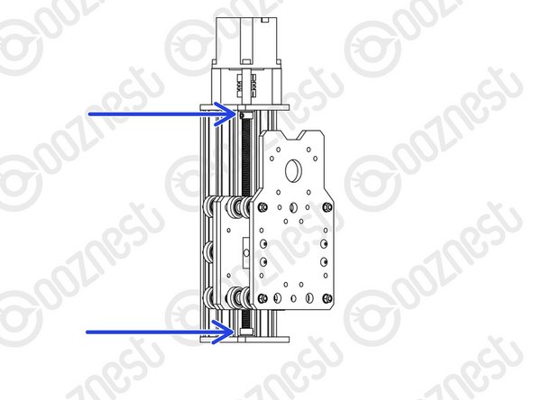
by the picture the first z end plate should be the bottom (red arrow) not the
top, so the top should be left loose
Peter Ashby - Resolved on Release Reply
-
-
-
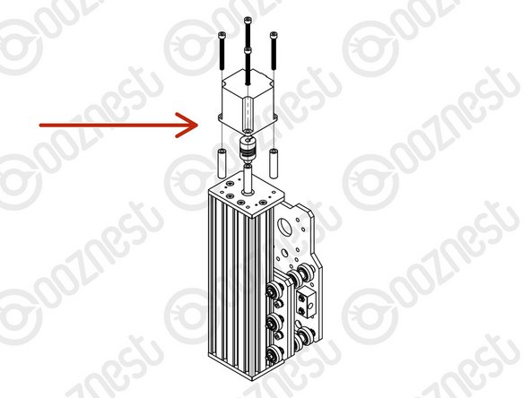
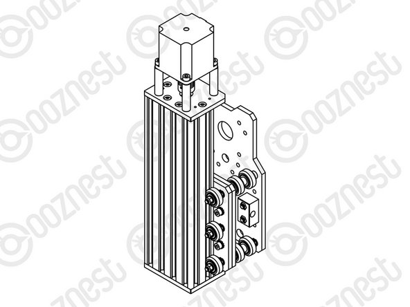
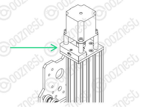
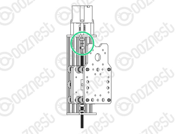
Slide the 1/4” side (the side with the smallest hole) of the Flexible-Coupler onto the shaft of the Stepper-Motor. Don’t tighten it down at this point.
-
Attach the Stepper-Motor to the threaded holes on the top Z-End-Plate using 4 x M5-Cap-Head-Bolt-50mm and 4 x Aluminium-Spacer-40mms.
-
Orient the Stepper-Motor so that the wire is towards the back of the X-Carriage-Assembly.
-
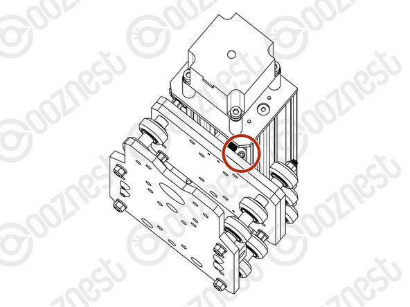
If you have the Touch Probe, follow Step 3 of Assembling Your Original WorkBee XYZ Touch Probe to attach the left side of the Stepper Motor.
-
In this case it should look like Image 3.
How can I secure the 50mm bolts if I’m using a touch probe, the bolts are just not long enough to go through to the holes in the extrusion
Stephen Freeman - Resolved on Release Reply
Hi Stephen,
Thanks for your email. Not sure what you mean, the 50mm bolts should still be long enough.
Robert -
I have installed the touch probe, but tightened the bolt under it, I am prepared to have to remove the touch probe and loosen that bolt again if necessary.
Peter Ashby - Resolved on Release Reply
If you install the touch probe when it says you aren’t able to tighten the end plate so I left the the touch probe off and built it as if I hadn’t got one then once the end plate has been tightened etc I just installed it as if I’d bought it as an add on.
Richard Huntington - Resolved on Release Reply
-
-
-
Slide the Lead-Screw-Z through the bottom Z-End-Plate. Then slide on a Flanged-Radial-Bearing (facing downwards) - ->- - Bearing-Shim - ->- - Lock-Collar.
-
Thread the Lead-Screw-Z through the Z-Axis-Nut-Block. Then slide on a Lock-Collar - ->- - Bearing-Shim - ->- - Flanged-Radial-Bearing (facing upwards).
-
Continue threading through the Lead-Screw-Z until it is touching the Stepper-Motor shaft.
-
Position the Flexible-Coupler so it is half on the Lead-Screw-Z and half on the Stepper-Motor shaft.
-
On the Stepper-Motor side make sure the Flexible-Coupler grub screw is on the flat portion of the Stepper-Motor shaft. Once in position, on both sides tighten the clamping bolts first, then the grub screws.
-
Top & Bottom, slide the Flanged-Radial-Bearings along the Lead-Screw-Z until they seat fully in the Z-End-Plates.
-
Slide the Bearing-Shim against the Flanged-Radial-Bearing, and finally slide the Lock-Collar so it is firmly against the Bearing-Shim. Lock each Lock-Collar in place using the grub screw on the side.
-
Locate the four bottom M5-Button-Head-Bolt-16mm that were loose from Step 9. These can now be fully tightened. This will remove any play that may be present.
Further to my last comment, I also found that the bottom locking collar came loose after tightening the bottom bolts from Step 9. I reckon the grub screw had been sitting on the apex of a thread and it was popped-off into the next groove. In the end I gave up with using the end plate to compress the mechanism and just made sure the collars were pressed hard apart before tightening the grub screws. I'm just a beginner at this, and I need to respect the years of experience that's gone into this machine, but this process of eliminating slack seems awkward. Could the leadscrew be tensioned rather than compressed? Is there an alternative to the locking collars, locknuts perhaps?
Hi Peter,
The amount of compression, only needs to be enough to remove any backlash in the system. So if you have no backlash without doing the compression steps, then that is ok.
Robert -
On completion of this step the leadscrew had notable tight spots, and one full turn of the bottom bolts from Step 9 had seemed to be a lot of compression on the lead screw that transfers right through to the stepper motor. I played around with the tightening sequence for half an hour and mostly got rid of the tight spots by leaving a 1mm gap between the ends of the shafts inside the coupler. However I can see that this means that upwards force on the spindle during operation will now be taken by the top flanged radial bearing rather than the stepper motor bearings - but that's good isn't it?
One of my lock collars came loose and the screw is missing. Can i get replacements for either the collar or the tightening screws?
Hi Chris,
Please contact us here https://ooznest.co.uk/help/ where we will be able to assist you further.
Thanks.
Hi
I'm at step 11 Z-Axis Lead Screw fitting. The Z Lead screw will not fit through the Flange Radial Bearing, Z Lead Screw (as does the other lead screws) measures up at 8.0mm the Flange Radial Bearing measures at 7.9mm. Can you tell me what to do about this please, there's no indication the Flange Lead Bearing is meant to be an interference fit.
Look forward to your reply
Regards Richard
Richard Gething - Resolved on Release Reply
Hi Richard,
Can you contact customer service who will be able to resolve this issue for you https://ooznest.co.uk/help/
Thanks
I think it would be good if you had an image of the Flexible-Coupler showing what is “clamping bolts” and what is “grub screws”. Being a non-english speaker, it’s difficult to understand the difference. It’s also not clear how the mechanism of the Flexible-Coupler works - why is both clamping bolts and grub screws used, and what are they used for.
If your eyesight isn’t what it was then this may help…The Flexible coupler has FOUR little screws. It looked to me like there were two screws going all the way through to the other side. (As instructions) Make sure the tiny grub screws are screwed onto the flat part of the stepper motor shaft.
-
-
-
Firmly hold the Assembly, and check for any up and down play in Extrusion-D.
-
If there is any, this is due to backlash in the Z-Axis-Nut-Block.
-
The set screw which was inserted in Step 3 into the Z-Axis-Nut-Block can be tightened to remove backlash.
-
Do not over tighten this, as it can make the Lead-Screw-Z difficult to turn. You can test this by rotating the Flexible-Coupler by hand.
-
It should require a small to medium amount of force. This will need to be checked once the router is attached, and periodically checked when in use.
What do you use to adjust Lead screw, also its very tight to access. Is there anything I can do to make it easier to access?
Michael Eckles - Resolved on Release Reply
-
-
-
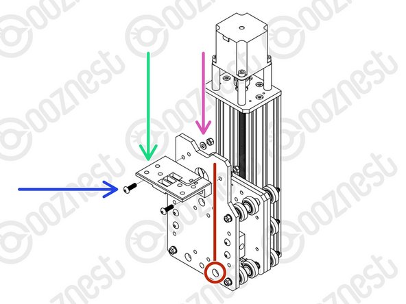
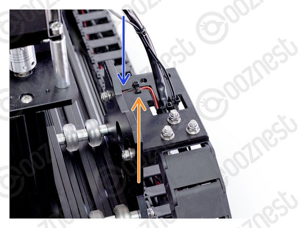
Feed the wire of Limit-Switch-2 attached in Step 5 through the hole opposite on the X-Plate-Back.
-
A Drag-Chain-Mount needs to be attached to the X-Plate-Back.
-
Insert 2 x M5-Button-Head-Bolt-16mms through the Drag-Chain-Mount.
-
Notice on the back of the Drag-Chain-Mount there is a slot. The Limit-Switch-2 wire goes up the X-Plate-Back and through this slot.
-
Put the Drag-Chain-Mount against the X-Plate-Back with the Limit-Switch-2 wire in this slot.
-
Then add a Precision-Shim and M5-Nyloc-Nut on the opposite side of the X-Plate-Back.
-
Tighten the Drag-Chain-Mount against the X-Plate-Back
Note the rotation of your Limit switch. I got confused and put it upside down in the previous step with the switch inwards instead of outwards.
Nisse Bergman - Resolved on Release Reply
Would it be allowed, with the syntax of your handbook, to change
“Notice on the back of the Drag-Chain-Mount there is a slot. The Limit-Switch-2 wire goes up the X-Plate-Back and through this slot.” bullet color to red instead of orange? To show its relation to first step but also to the RED line where the harness should go?
-
-
-
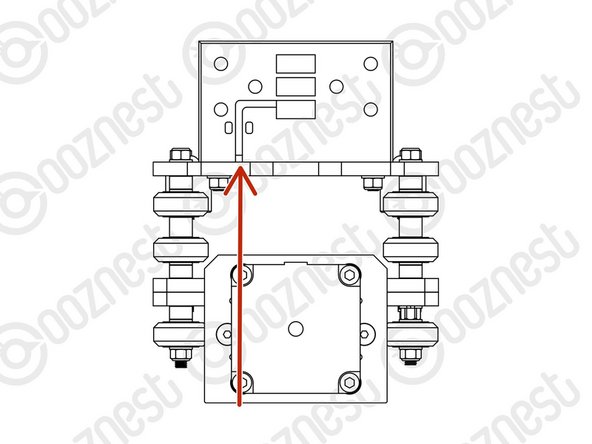
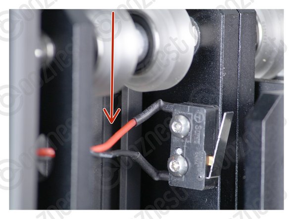
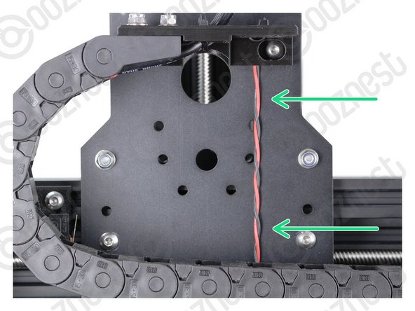
Pull the Limit-Switch-2 Wire taut all the way from the switch to the Drag-Chain-Mount.
-
Image 1 shows it taut in-between the Solid-Wheels.
-
Image 2 shows it taut up the back of the X-Plate-Back.
-
Image 3 shows it inside the slot on the Drag-Chain-Mount.
-
Make sure it is taut the whole way.
-
Use a small cable tie to secure it to the Drag-Chain-Mount.
-
Make sure your Limit-Switch-2 Wire looks exactly like the images.
-
Double Check - Make sure your Limit-Switch-2 Wire looks exactly like the images.
The bag of cable-ties in my kit was loose in the main box. It took a while to find them as they're not listed on the WorkBee Box Cheat Sheet.
Andrew Greensted - Resolved on Release Reply
Hi Andrew,
Apologies for the inconvenience caused. I will pass your feedback along and see if we can get that updated.
Thanks.
Hello. The Spelling Police here. Slight error in the text, it should be taut rather than taught. They sound the same but have completely different meanings.
Matt Curtis - Resolved on Release Reply
Slight variation and picking up on previous comments...a small piece of 2.5mm twin and earth outer sheathing (1.5mm is too small) spilt down and the wires removed. Slide onto the cable close up to the switch and trim to the hole in the X plate. Close up the split with hot glue and glue the end of the sheath to the X plate hole. I also added the matchstick to the cable tie and a blob of hot glue for good measure.
Laurie Wilson - Resolved on Release Reply
Reading all the comments about the limit switch wire coming loose and getting tangled in the wheels I designed and 3D-printed a wire shroud thingy that should prevent that from happening. If anyone is interested it can be found here: https://www.thingiverse.com/thing:555476...
Thanks to the comments here I decided rather than hot glue to install a small piece of matchstick in the channel, just at the point where the cable tie us, thus ensuring the cable tie is not only keeping the wire in the same area, but also holding it in place. This could be incorporated into the design of the chain mount rather than having to use a piece of wood.
After slightly having to bend the wire of the switch I later found the switch did not work. It was a result of the soldered wire snapping and had to re-solder both. Not a big issue but gave me a start on Trouble shooting diagnoses.
John Smith - Resolved on Release Reply
I put a piece of plastic tubing around the wire between the wheels and hot glue it too the X plate. It prevents the wire getting caught up in the wheels should it work loose from the cable tie on the drag chain mount. I have had more problems with this switch wire than any other and its a devil to get too once assembled.
Stephen Wright - Resolved on Release Reply
I think the drawing in Step 5 is showing the (metal) part of the “switch” as facing in the opposite direction to the close-up photo here in Step 14 - image 1?
Andy Bennett - Resolved on Release Reply
Hi Andy, yes you are correct. - good spot! The orientation of the switch is not important, however, we will still get that fixed. Thanks
Robert -
-
-
-
Clear the table, you are going to need room. Keep this X-Carriage with you.
-
Guide Complete - Proceed to 4. X-Gantry Assembly
I have a problem with the z axis not being able to move up enough to operate the z axis limit switch. The clamping collar on the inside catches the structure and stops movement and thus the stepper motor starts jumping as the controller continues to try to raise it (until I hit emergency stop). I notice a hole in the end plate where the limit switch should make contact. Am I missing something?
Steve Brankin - Open Reply
Hi Steve, can you please contact us via https://ooznest.co.uk/help/ - please include some pictures of the problem / assembly so we can help check where it may stem from?
Peter -
-


Thanks for following the guide. Any issues, please contact us!
Thanks for following the guide. Any issues, please contact us!
Cancel: I did not complete this guide.
92 other people completed this guide.

7 Comments
This applies through all the guides…it would be useful to start each step with the list of parts needed in the step. We find we have to read the step to find all the parts we need, then read again to see what we need to do now that we can see what the parts look like, then read again when we do the necessary tasks.
Chris McMahon - Resolved on Release Reply
I find that the wheels don’t seem to all locate perfectly in line with the extrusion D. This means a couple don’t make contact when it’s in operation or spin oddly. Doesn’t seem to be making any issues as the other 4 make contact and it travels the Z axis fine, but is there a way of making sure all wheels are located snugly?
Hi George,
Have you tried doing the outer most wheels first, getting them perfect, then just bring the middle ones down onto the extrusion slowly just until touching, but not too much the it effects the outer two.
Robert -
in the exploded view in step6 the aluminium spacers and precision shims are shown the wrong way round.
Frank Triggs - Resolved on Release Reply
what is the name of the plate?
Mark - Resolved on Release Reply
Hi Mark,
It is called the Z-Plate
Thanks!
Robert -
Please add a note that the eccentric spacers fit one side only.
Add a second exploded drawing with item bubbles identifying hardware. Item bubble number should correspond to a distinct number from the bill of materials and include that number on the hardware kits/bags instead of using the names (or with the names).
Include torque values for screws.
Jacob Weiand - Resolved on Release Reply
i’ve had the same issues with the button head screws.. i had to resort to hammering torx head bit into a partially rounded hex to remove on of the screws
Neil Dilly - Resolved on Release Reply
I had issues with the M5-Button-Head-Bolt-30mm in this step. Two different types were supplied, one with TWE A2-070, the other with no markings. The ones without markings would not hold the allen key when trying to overcome the initial friction of the nylock nut. I now have one wheel stuck half on and half off.
Colin Turner - Resolved on Release Reply
Hi Colin,
Thanks for pointing this out, we are going to chase this down with the supplier. Let me know if you need any replacements.
Robert
Robert -
PS. In this case 6 mm text rotated 90° to the outside/right
Emil - Resolved on Release Reply
I entered all six screws, added a tape on the back side (so it would not drop out), then I did all six assemblies at once. I aligned all Eccentric-Spacer-6 mm towards the same direction to save time for later adjustment.
Emil - Resolved on Release Reply