
-
-
This step requires the removal of existing parts on the Z-Axis Stepper-Motor
-
Remove the left 2 x M5-Cap-Head-Bolt-50mm.
-
Slide out the 2 x Aluminium-Spacer-40mms.
-
-
-
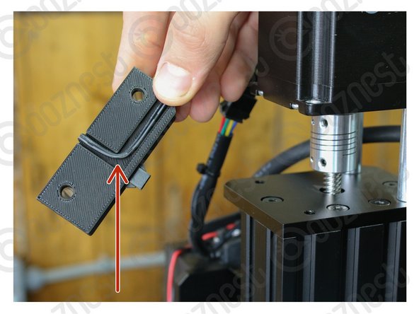
Insert the 2 x Aluminium-Spacer-35mm into the Touch-Probe-Mount, pushing them in until they can go no further.
.It would be useful to have a radius on the internal corner of the cable recess of this part.
Colin Turner - Resolved on Release Reply
-
-
-
Tuck the wire underneath the Touch-Probe-Mount as seen in Image 1.
-
Place the Touch-Probe-Mount with the 2 x Aluminium-Spacer-35mm under the Z-Axis Stepper-Motor.
-
Using the previously removed 2 x M5-Cap-Head-Bolt-50mm secure the Stepper-Motor.
The probe should be orientated so that the tucked-in wire is inside, and the port is outside. diagram shows a hole facing out. frustrating
James Hall - Resolved on Release Reply
Hi James,
Thanks for your comment, I am not sure I get what you mean, as the picture looks correct to me.
Robert -
Same issue as dermot. in image the bolt under plastic mount and counter sunk. on both my plates there is no recess for counter sinking these bolts. can this be removed or will it cause issue down the line
brian mclarnon - Resolved on Release Reply
Hi Brian,
Can you check your end plates as one side on both plates should be countersunk.
Thanks
remove m5 low profile 15mm under probe plastic mount as it does not let mount sit flush
Dermot Thorpe - Resolved on Release Reply
Hi Dermot,
That shouldn’t be needed. There must be something wrong with your plate or bolts you are using.
Best Regards
Ryan Lock
If you purchased the touch probe as part of the kit, this is best done at stage 9 of the X-carriage Assembly.
NB - You don’t use the existing M5 Low Profile Bolts as they are too short - 2 x 50mm bolts are provided in the touch probe kit.
Steve Johnston - Resolved on Release Reply
-
-
-
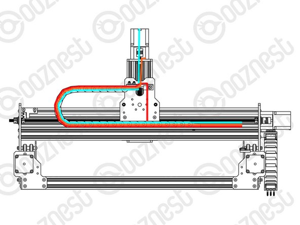
Feed the Touch Probe Wire through the Drag-Chain-Mount and then through Drag-Chain-X so it comes out the Fixed End.
-
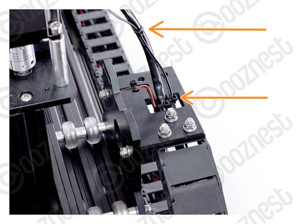
Secure the wire to the Drag-Chain-Mount using a small cable tie. Then secure it along Motor-Wire-6.
-
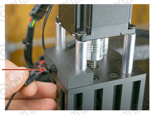
The connector on the wire is keyed, so there is only one way which it can plug in.
-
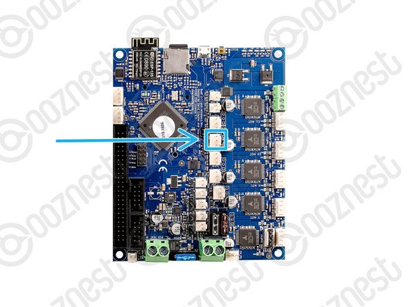
Plug in the Touch Probe Wire following Image 2.
Our Touch Probe panel only works with the standard Duet ports, so it would be best to move something else to E2-E6 and use the probe on the normal Duet ports.
Robert -
What If E0 and E1 pins are taken? Do I have to connect it to E2->
Janne Mäkelä - Resolved on Release Reply
The touch probe wire ISN’T the wire on the touch probe (yesss. I thought it was?!) The touch probe wire is the wire with the white connector hanging off the touch probe mount. The wire on the actual metal touch probe has a black connector which connects to the the bit sticking out of the touch probe mount (photo step 3).
Excellent, makes sense now! Black Touch probe cable (5cm Aluminium square plate) doesn’t get fed intot the controller box.
-
-
-
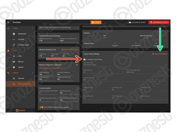
Enable The Touch Probe.
-
Press 'Reset to Defaults' to make sure we have the correct settings for the Original WorkBee XYZ Touch Probe.
If done in the order of this guide, the Touch Probe Window does not appear! To get the window to show up in WBC you need to disable then re-enable the Touch Probe!
Alan Foster - Resolved on Release Reply
When using the touch probe, it works great with the Z and Y axis but when it tries to find the X axis it raises 5 mm above the plate so does not touch it.
please advise
Hi John,
That should not happen when running the sequence, are you able to send a video into us via our Help section - https://ooznest.co.uk/help/ Thanks
also worth noting the web interface version on the board supplied June 2020 is 1.22.6, not sure what version the guide is written for
Pete Franklin - Resolved on Release Reply
The guide is written for WorkBee Control. This should be the current control software version after setting up the machine.
i too am unable to find the touch probe setting… my firmware is 2.03 according to m115 through the g-code console! and this is AFTER uploading the workbee firmware download!
FIRMWARE_NAME: RepRapFirmware for Duet 2 WiFi/Ethernet FIRMWARE_VERSION: 2.03 ELECTRONICS: Duet Ethernet 1.02 or later FIRMWARE_DATE: 2019-06-13b2
Pete Franklin - Resolved on Release Reply
Can you explain what the x,y, and z dimensions are vs the x,y, and z offsets? I have a different plate I am using and the edges are 7mm offset in y and z and the z height of the block is 22mm. Just wondering which fields to enter these numbers in. I can tell if they are for the moves or for offsetting the probe positions or both?
Thanks
Dave Gement - Resolved on Release Reply
Hi, The X,Y,Z Dimensions, are the dimensions of the probe in total. The offsets, is the thickness of the material remaining, after removing the inset for the corner. So i think yours would be X 7mm and Y 7mm. For Z, the dimension would be 22mm, not sure about the offset, without knowing how far is has been recessed.
I have a different window when connecting to the machine, with different setup, white background and, more importantly, no reference to the touch probe under settings… Am I doing anything wrong? That aside the machine works well
Giorgio Caenazzo - Resolved on Release Reply
-
-
-
Plug your Touch Probe into the Touch Probe Mount Connector.
-
In WorkBee Control go to Control > Dashboard.
-
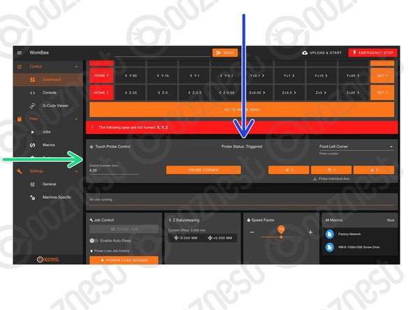
You will now see the panel 'Touch Probe Control'
-
You can view the status of the Touch Probe.
-
Clip the Crocodile Clip to an End mill not in the Router Head, and hold it touching the Touch Probe like Image 3
-
The status of the Touch Probe should change to 'Triggered'
-
If it does not, verify your wiring. Otherwise Contact Us.
Can the Touch Probe be plugged in/out of the Touch Probe Mount Connector whilst the Duet is powered up?
Chris Davies - Resolved on Release Reply
-
-
-
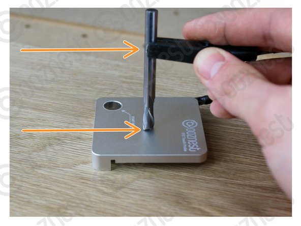
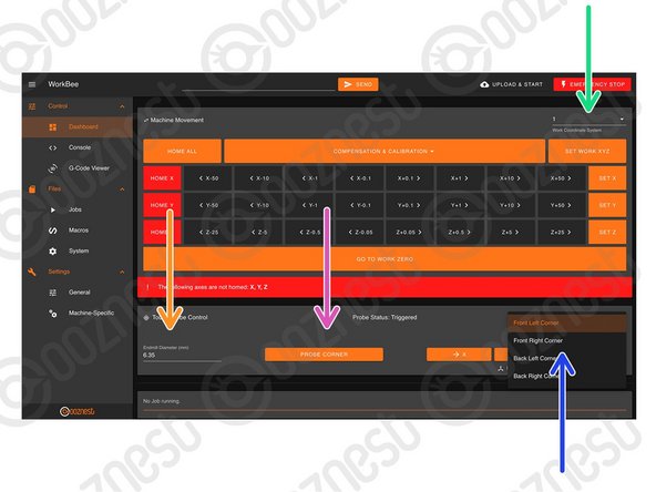
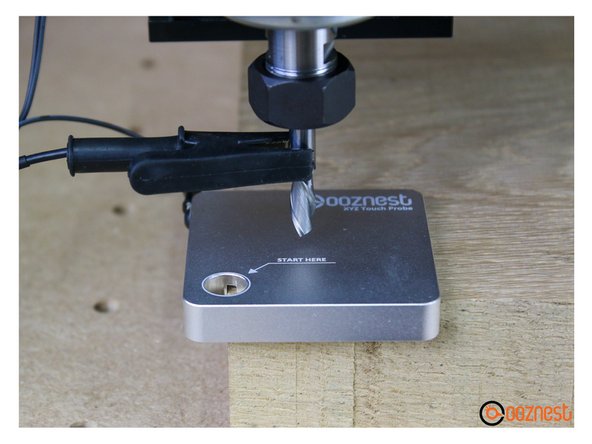
Locate your Touch Probe over the corner of the material. Jog the machine until it is within the 'START HERE' Hole, roughly level with the surface of the Touch Probe. Connect your End mill.
-
Select the Work Coordinate system you would like to probe in.
-
Select the Corner you have the Touch Probe on.
-
Define the Endmill Diameter.
-
Press Probe Corner to begin probing.
-
Wait until the 'Probe Successful' confirmation.
-
Unclip the Touch Probe from the End mill and Touch Probe Mount.
-
Press 'Go to Work Zero'. Your machine should be perfectly aligned with the corner of the material.
\hi everytime I click “probe corner” the z-axis lifts away from the probe and then lowers into the spoiler board, any ideas?
ali@curvemedia.uk - Resolved on Release Reply
Hi Chris,
Please refer to the first point on Step 7 on probing your first corner ‘Locate your Touch Probe over the corner of the material, jog your machine until it is within the 'START HERE' Hole, roughly level with the surface of the Touch Probe. Connect your Endmill using the Clip.’ You should find this works!
Ryan Christy - Resolved on Release Reply
Following this I get error message M98 Pprobe.g
G0/G1: target position outside machine limits
Wayne Elmore - Resolved on Release Reply
I had this and it was because I had previously homed the CNC so Z was sat up high on its limit. The likelihood is that you will have moved X/Y to a more suitable location for doing the set up but not Z!
-
-
-
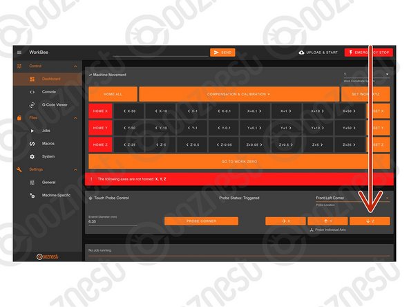
Follow these Steps to Probe the Z-Axis Only.
-
Connect your Touch Probe and End mill like previous.
-
You can either have the Touch Probe on a corner with the End mill over the middle of the probe like Image 1.
-
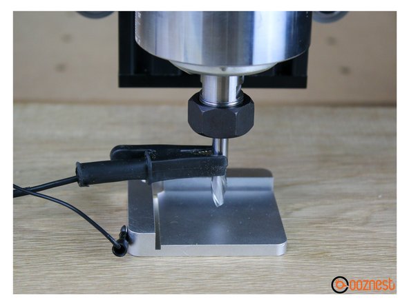
Or you can have the Touch Probe anywhere on your material, but upside down with the End mill over the inset portion like Image 2.
-
This time just press the Probe Z button.
Hi Glen,
When probing the Z-Axis only, are you using the probe upside down like this image: https://d3t0tbmlie281e.cloudfront.net/ig...
Hi Glen,
Ok, if it is turned over, are you probing the thinner portion of the probe.
Also when the probe completes, you do not need to press the ‘Set Work Zero’ button.
Robert -
Hi guys i used the probe to set the height of the z axis only, set the work zero and when i ran the job the end mill ran about 10mm above the work peice. But if i set the height manualy on top of the job its fine. I take it you dont have to callibrat the probe.
Thanks Glen.
Mr Glen Seagars - Resolved on Release Reply
Hello Team Ooznest. Under what circumstances should we change the "Touch Probe Trigger Level" (Active Low or Active High) in the Touch Probe Settings ? Does it have anything to do with the upside-down position of the probe when we probe a corner or a flat surface ? Thank You.
Hi Remi,
If you have our Touch Probe, there is no need to ever change it. That setting is just for people using custom touch probes.
Robert -
Did the corner probe check and it completed the z touch but as it moved towards the y it failed to stop and I had to hit emergency stop?
Can you suggest a reason?
JSR Sculpt - Resolved on Release Reply
Hi, This could be caused by the WorkBee Control Firmware and Version not being up to date - can you get in touch via our help page here and we can assist further - https://ooznest.co.uk/help/#tab_technica...
I’m confused as to if the plate needs to be the right way up or upside down. There are two images
Wayne Elmore - Resolved on Release Reply
-


Thanks for following the guide. Any issues, please contact us!
Thanks for following the guide. Any issues, please contact us!
Cancel: I did not complete this guide.
45 other people completed this guide.

23 Comments
Hi, just setting up the touch probe. However, I am using the black box. The box has a probe space and a three wire connector, as the probe is only two wire, can I just confirm I need to wire power and signal and leave ground blank? Thanks. Mick
Mick Cockburn - Resolved on Release Reply
Hi Mick,
The Ooznest XYZ touch probe operates like any other Normally Open Touch Probe so it would connect in the same way as a Z Touch Plate. Connect the 2 cables to the GND and SIG, leaving the middle empty, as per this image: https://docs.openbuilds.com/doku.php?id=...
Thanks.
Hi Graham,
The touch probe does require some space around it to be able to move and check the X&Y, is your material very close to the front left of your working area? Can you push the material back and to the right further?[br]
You can also set the XYZ without the touch probe, following step 5 here: First Project
Thanks
Hi Ryan
I have had my 1500 x 1500 machine working and realized that to cut the larger sheets and set a larger working are i needed to update my firmware. Before i did the update the xyz probe worked fine and could could cut small sheets without problems. After the update it will only detect the Z axis and then shows an error . If i try manually to probe it fails and does not clear the probe.
Do i have to manually create a macro to now perform the action needed? If i try to manually set the machine to work zero it still shows an error an shows ( cutting outside of machine perimeters)
Im only trying trying to cut 1220mm x 1220mm
Thanks
Graham
Hi Ryan
I have a 60 Deg bit how do you probe the corner , when i tried it the bit gos half way down the angle only so gives an incorrect centre.
Thanks Glen.
Mr Glen Seagars - Resolved on Release Reply
Hi Glen,
With VBits, you need to probe the corner first using a normal endmill. Then just probe the Z with the VBit.
Robert
Robert -
Can I contact you another way so I do not have to spam this channel? My touch probe is 5 mm thick and the end mill traverse 10 mm back. This happens regardless of the thickness I specify on the touchpad. I can send a movie sequence.
Örjan Johansson - Resolved on Release Reply
I needed an offset in the z-axis so I changed the height of the touch probe in the configuration menu. The height still remained unchanged. Can I change the value of the thickness in any of the configuration files?
Örjan Johansson - Resolved on Release Reply
Hi Orjan,
We have reviewed the code, and can confirm it is adjusting for the Z Dimension and offset correctly. You should start the probe with the end mill flush with the top surface of the touch probe. It will always traverse 5mm above this point regardless of thickness.
Robert -
Has changed values for the thickness of the touchpad, but sees no changes in probe.g
/Örjan
Hi Orjan,
Thanks for your comment. It is written to probe.g when you run the probing sequence. We will check the code and confirm. Thanks
Robert -
Yes, I have changed there, but there will be no difference in the movement of the z-axis. It seems that the change is not written into any file. In which configuration file can I see the value?
Hi Orjan,
Thanks, yes it is possible. Under Settings > Machine Specific. Z Dimension is the overall thickness, and Z Offset, is the material remaining with the inset taken out.
Robert.
Robert -
Hello,
Could a macro be developed to allow the touch probe to be used to calibrate the CNC machine by calculating the steps/mm and updating it using the M92 command.
Thanks
Pete
Hi Peter, it could be used to do it for the Z-Axis, but not X and Y. You would have to make sure the touch probe is square with the machine, and we have a better technique in the works :) Ryan
Hi Ryan
Im trying to test the probe .
The Z axis moves up ( rather than down) when probing for the Z point.
If I push if I jog -5 the z moves down.
How do I correct the direction ?
Edwin Kalish - Resolved on Release Reply
Hi, sounds like your touch probe wire is not making a connection, so it thinks it is already triggered. If you email sales@ooznest.co.uk we can look into it further. Best Regards Ryan Lock
Hi Ryan,
I want to use your touch probe on an MPCNC with your Firmware and WebControl. I bought your touch probe alredy and now I want to test it. The step 6 test is ok, but the axis are moving in the wrong way. For Z axis e.g. it moves up instead of down. It will stop if I touch the endmill, so the connection is ok. The machine ist working well, so I do not understand why the moving direction is contrariwise in this specific function.
Is the a way to change this?
Thank you very much
Best regards
Gerd
Gerd Lobmeyer - Resolved on Release Reply
Hi Gerd, thanks for your comment. On your MPCNC, if you press Z+ which way does the Z-Axis endmill move? Ryan
Hi Adam, please contact sales@ooznest.co.uk and we can sort you out.
Ryan Lock - Resolved on Release Reply
All the 40mm spacers that came in my kit are measuring 38mm. Is this ok? Because now the stepper motor doesn’t sit flat, it’s off by 2mm!
Adam J Barnett - Resolved on Release Reply